The ABB units need about 6-9A inrush current. The relays on the normal Arduino boards should be able to cope with that.
No they wont get out of balance. You draw this current during 250ms when the breaker trips. So just hook the breaker up to half the pack through the Relay
Thanks for your help so far! Last question (for now ), I’ve seen some breakers from midnite solar, 200a for around $120 brand new. Which route should I go? used ABB or the midnite solar ones new?
Cant say which one is best for you. I dont have access to midnite where i live and havent tested them. For me the ABB units are rock solid but they are also very big. I have both S5 and S3 here and the S5 is a beast!!
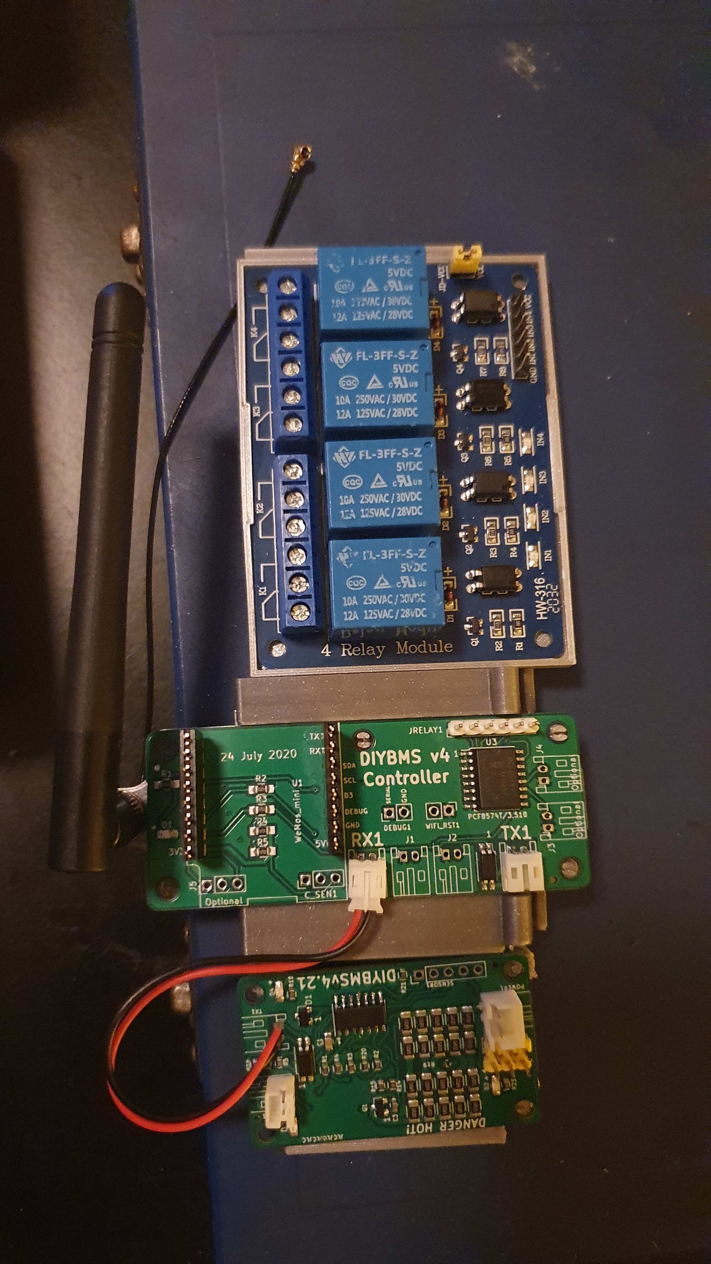
Found some mounts on thingverse and redraw some bits to get them on a dinrail, attach the antenna and make it modular, still need to do some redrawing and modifications
The MOSFET can support over 6Amps, however how do you dissipate the amount of heat that will generate?
Only you can determine if the balancing current is enough for the size of the battery you are constructing, as you mention you can split larger packs down into multiple strings. Up to 4 are supported on the current controller (16 with the new experimental software).
The ESP8266 doesn’t have many IO pins, most are already used hence the PCF chip - this also allows higher current on the pins and also removes the possibility of destroying the ESP chip when driving external devices.
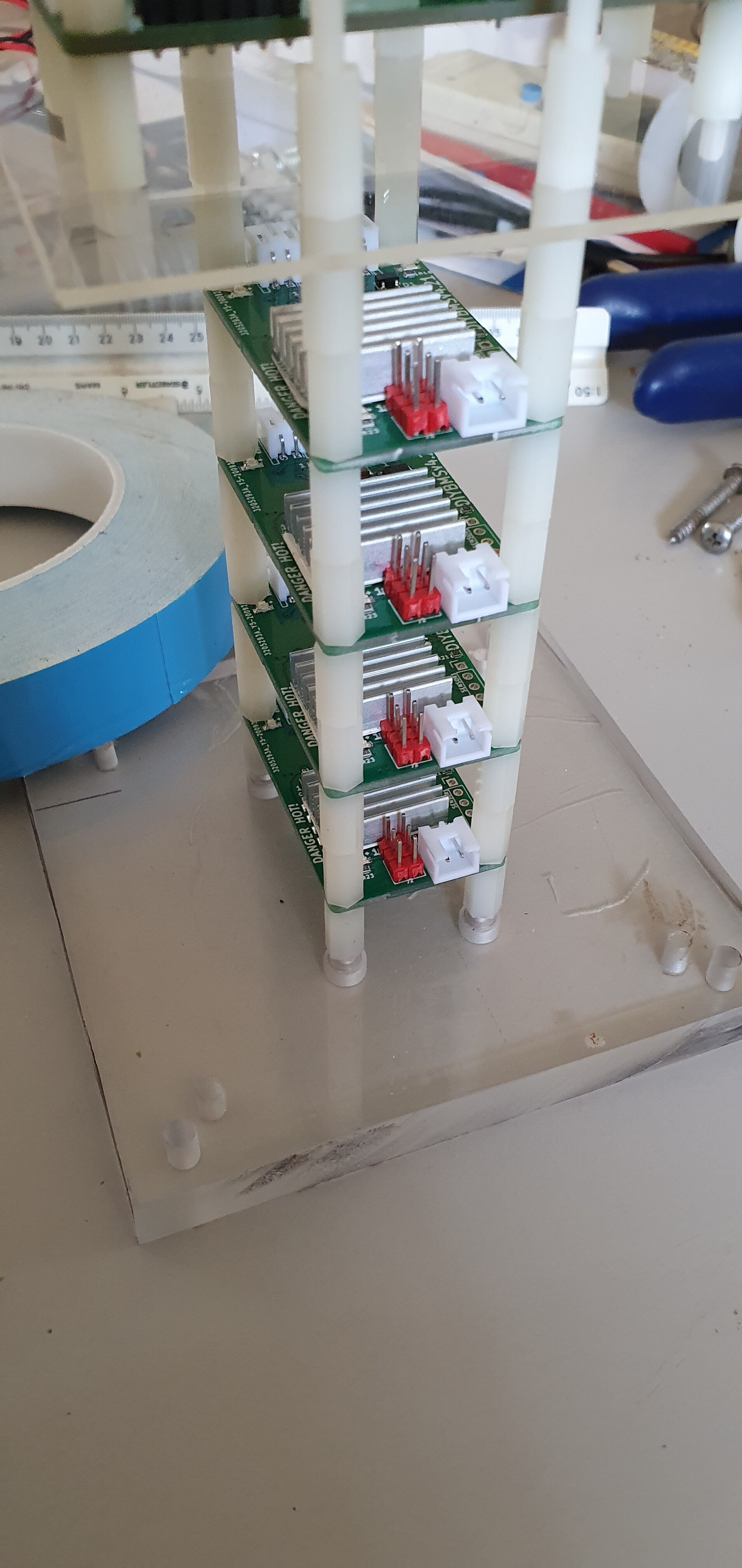
Had a module which seemed to ever so slowly drain the battery it was attached to…can it be caused by my not so pretty solderwork on the attiny?! What also caught my attention was that this module was always
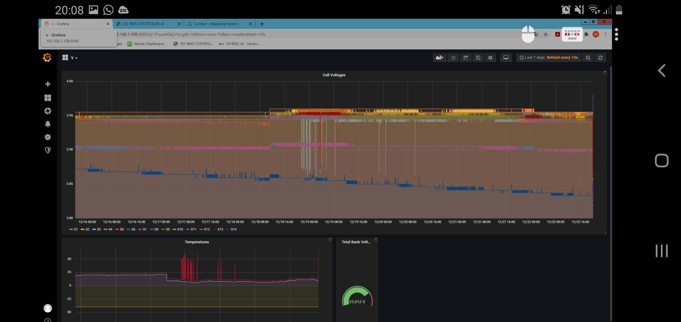
3 degrees warmer then the rest (also when i measured temp with an ir thermometer. Screenshot_20201222-200856_Parallels Client|690x326
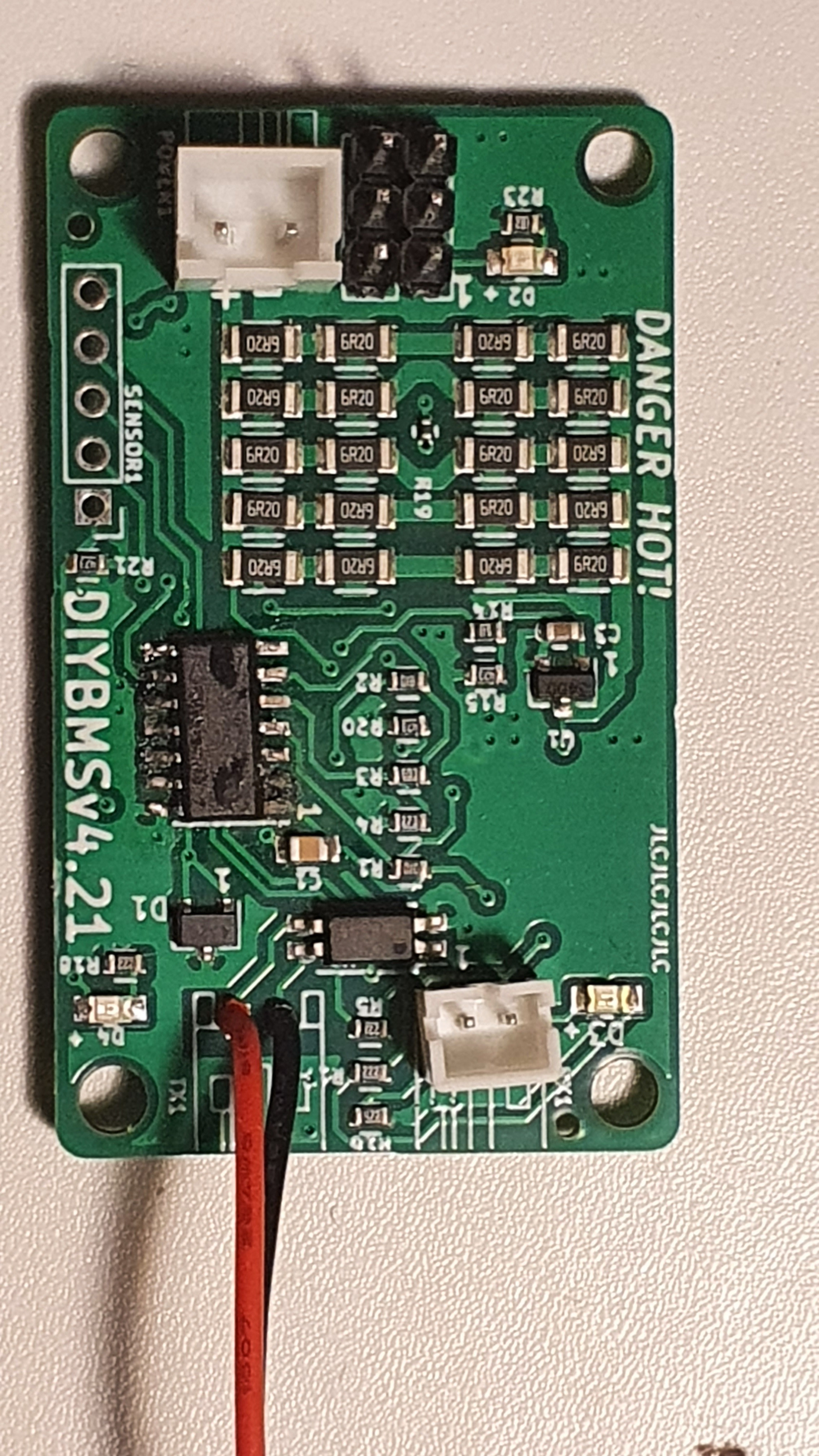
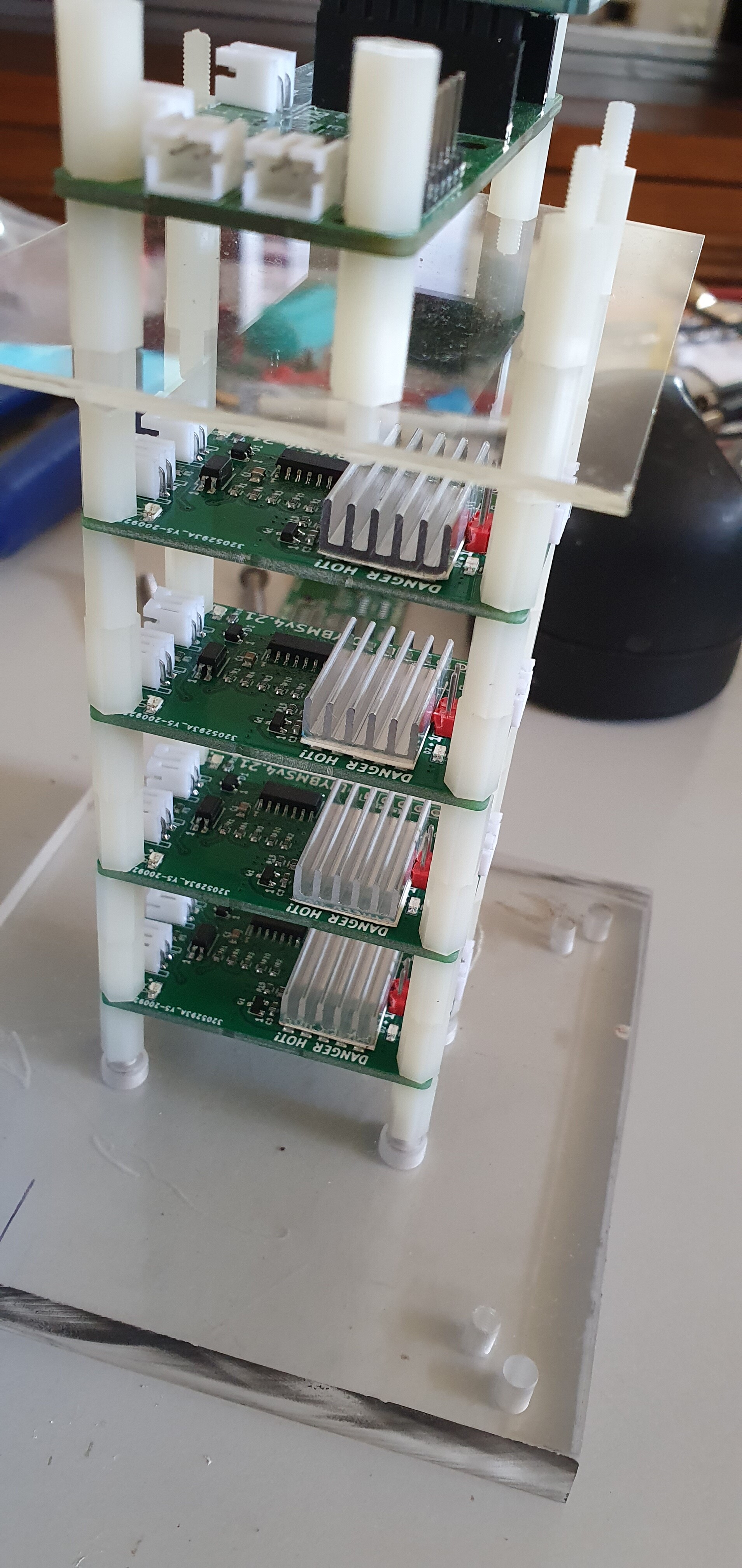
I am going to test a 4S lifepo4 battery over the Christmas break, I have placed a heatsink over the resistor bank and put a larger plug on the pcb for connection of the battery to allow a heavier wiring to the battery.
I brought a 20mm X 0.2mm x 25M/roll 3M Double-sided Thermal Adhesive Tape, and put 2 layers under the 20mm x 14mm x 6mm heatsinks.
So I suppose if one was planning to calibrate the ADC readings and only read cell voltages > 2.2V then the internal reference might be fine? Thanks for the info Stuart.
Perhaps, I don’t rate the internal reference on any of the ATTINY chips, the reference voltage bounces around with the supply voltage - the exact thing you don’t want.
Are you referring to the TL432 here (which I see in the jlcpcbassembly branch)? Looking at the datasheet (http://www.unisonic.com.tw/datasheet/TL432.pdf) I’m not totally clear on how much current it is constantly drawing from the cell. I would guess it’s “Minimum Cathode Current for Regulation” which is 0.6-1mA and that seems quite high to me.
Looking at the LM4040 (which I see in the master branch) - the operating current is bit lower at 45-60uA (https://www.ti.com/lit/ds/symlink/lm4040-n.pdf page 7) which seems more acceptable for smaller packs of cells.
What sort of acceptable idle current draw are you aiming for with v4? Thanks for walking through all this with me - appreciate your insights!
If you look at the circuit, the TL432 is driven from one of the ATTINY pins, so its only “on” for a fraction of a second whilst in use, then off for the remaining time.
The V4.21 boards sit idle most of the time consuming nano amps, and only a 5-10 milliamps when they process a packet of data for a brief moment. I spent a long time getting the power consumption as low as possible, based on the V3 DIYBMS design.
My test rig contains 8 single cell 18650 cells (less than 2000mAh each), and they take months to drain
down from the BMS module alone.
Hello guys .
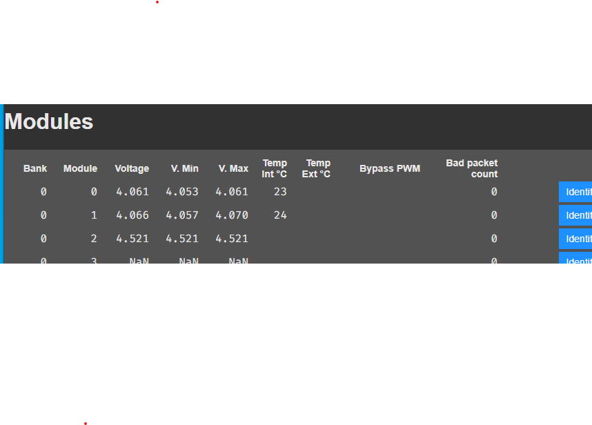
After mounting the V4.21 modules, and of the 30 that I have prepared there are two that give me an error, the voltage reading is 0.5V higher than the real one and also does not give a temperature reading.
I have reviewed the soldering of the Attiny again and again and I have also changed the D1 for a new one (finally, as JLC did not have and sent the modules without the D1, as a solution I put AZ432ANTR-E1 LCSC code C84139 with satisfactory results). Where do you think the error may be, what components should I check or replace?

 ), I’ve seen some breakers from midnite solar, 200a for around $120 brand new. Which route should I go? used ABB or the midnite solar ones new?
