The 500 error normally means you didn’t upload file system image.
However if you look in the main.cpp file, there are 4 or 5 lines commented out which you can enable to set the WiFi to what you want manually.
It’s in the setup() function.
The 500 error normally means you didn’t upload file system image.
However if you look in the main.cpp file, there are 4 or 5 lines commented out which you can enable to set the WiFi to what you want manually.
It’s in the setup() function.
I’ve seen it doing that as well, think it’s a bug in platform Io.
An extremely frustrating bug
Once you have it showing, don’t close the window whatever you do, you may never get it back.
If anyone has an issue with Windows 10 not recognizing their D1 Mini on any com port, (me),
I fixed it by installing the driver for USB to UART.
I have no affiliation with them, it just worked for me.
CP210x USB to UART Bridge VCP Drivers - Silicon Labs (silabs.com)
You must have the Silicon Labs drivers for both Windows and Mac OS. The driver is built into the Linux kernel, so another driver is not needed for any Linux flavour.
There are installation instructions for the SiLabs Driver in the ‘Learn’ section here: Learn→Electricity Monitoring→Using the Arduino IDE
If you are insisting on using platformio, ignore the first part about installing the Arduino IDE.
(Though my experience of platformio means I’m unable to recommend it and I advise the utmost caution when installing and using it. I would always recommend the Arduino IDE ahead of that.)
I am sure i am correctly uploading the code to the esp8266 using vscode / platformIO.
so just to make sure, I watched your YouTube video on flashing the esp8266 and as I thought I am doing it correctly as far as i can tell…
1st: set upload_port = COM"X"
2nd: select platformio.ini and go into platformio (within vscode)
3rd: expand drop down menu for “env:esp8266_d1minipro”
4th: Click Upload
and still the same issue. i can connect to the ssid the diybms is broadcasting but in the web browser if I go to its IP which is normally 192.168.4.1 and hit enter the address changes to “http://192.168.4.1/softap.htm” but still says:
“This page isn’t working192.168.4.1 is currently unable to handle this request. HTTP ERROR 500”
(very strange, I flashed the first esp8266 the same exact way and it worked fine last month)
trying to set my wifi credentials manually:
i found the WIFI settings in main.cpp to edit so it just connects to my WIFI but in not exactly sure which values to change besides the “ssid” and “passphrase” when just changing those and uncommenting the other lines as well, it compiles and uploads fine but the esp8266 is not connecting to my WiFi. doesn’t show up in my routers client list. do i need to change any other values?
//Temporarly force WIFI settings
//wifi_eeprom_settings xxxx;
//strcpy(xxxx.wifi_ssid,“xxxx”);
//strcpy(xxxx.wifi_passphrase,“xxxx”);
//Settings::WriteConfigToEEPROM((char*)&xxxx, sizeof(xxxx), EEPROM_WIFI_START_ADDRESS);
Step 5: Upload File System…
As noted in a few posts there are a few issues with PlatformIO not displaying the “Platform” or “Upload File System” option at times. If you can not find it you can try opening a command prompt in the project directory and run: pio run --target uploadfs
Thank you!
Once in the Alien head:
Left-bottom expand miscellaneous under quick access.
click on new terminal (should be PlatformIO CLI, not powershell)
Type in : pio run --target buildfs : and run that a couple of times. It took my machine twice to have it build successfully.
Then run : pio run --target uploadfs : This should upload the filesystem image even if you don’t see it.
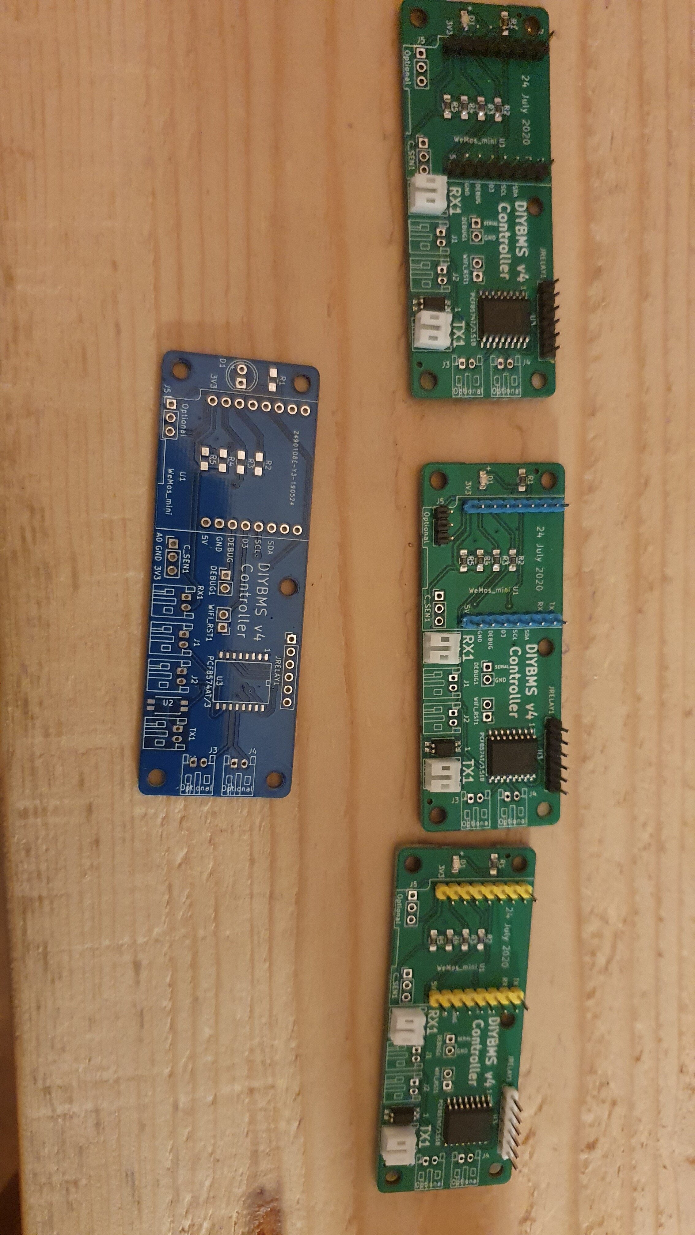
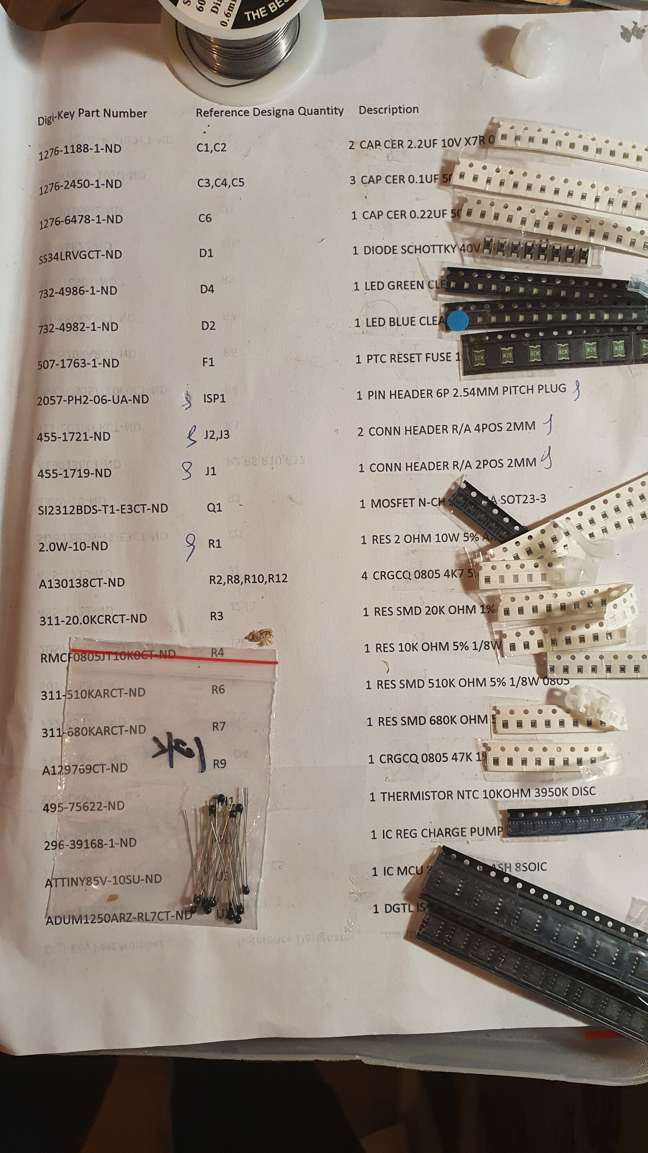
Controllerboards …
Because i ordered at jlcpcb and had to order at least 5, i got some left,
3 populated controllerboards
1 bare controllerboard
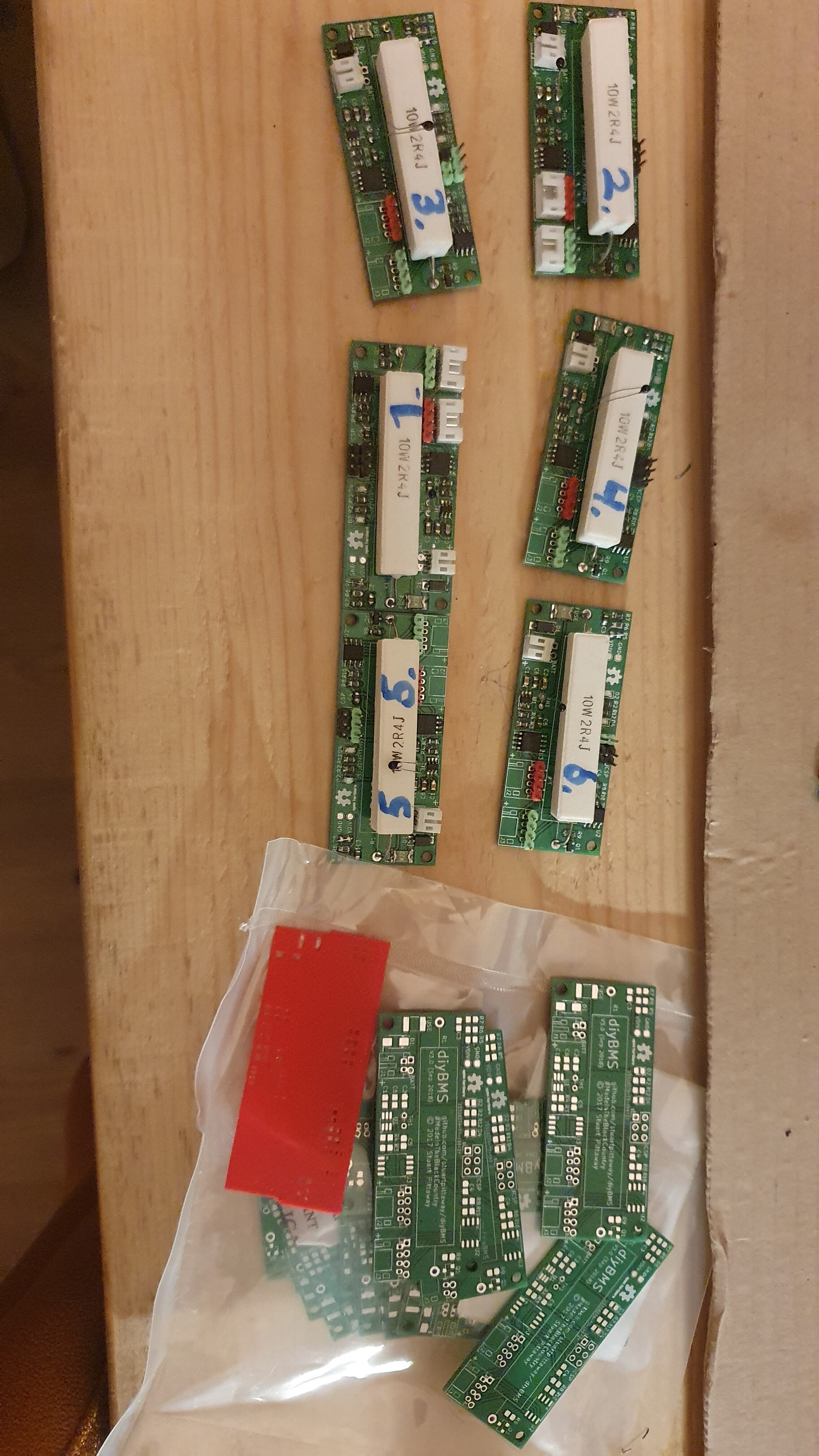
Also, i got 20 diyv3boards, 6 soldered up, the rest in parts( smd componenten, adum arz, attiny for diybms3, etc)
If interested let me know.
I am looking for thermistors for external temp sensing for the diybmsv4 modules.1 would be already be great, 20 even better 
I am in the netherlands, can post
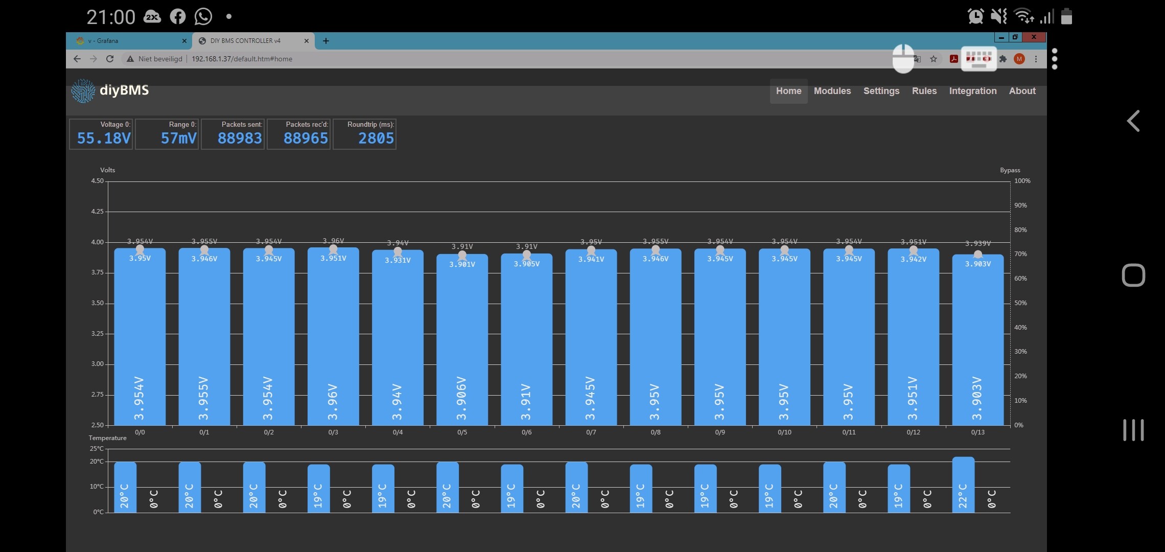
Hi Maarten, Grafana looks nice, what are your plans for it? Are you using this just for long term data retention? I could probably replicate a lot of what you are doing directly on the BMS controller/web pages.
Now that is an idea for your next controller. A micro SD card for logging cell data along with error logs.
It’s already on there! Part of the LCD screen.
MQTT is just a messaging protocol meanwhile Influxdb is a time-series database.
Influx is where you fetch data from to for instance Grafana to visualize the data.
DIYBMS does either data to MQTT or to Influxdb but the first does not stop the other For instance i always run my data via mqtt to Influx like
DIYBMS → MQTT → Influx.
So in your case Influx is enough and you have no use for MQTT. Personally i like Grafana alot since it can combine data from many sources. DIYBMS dashboard will always only show from that BMS itself  (I shouldnt say always but i guess thats how it should be to keep it simpel)
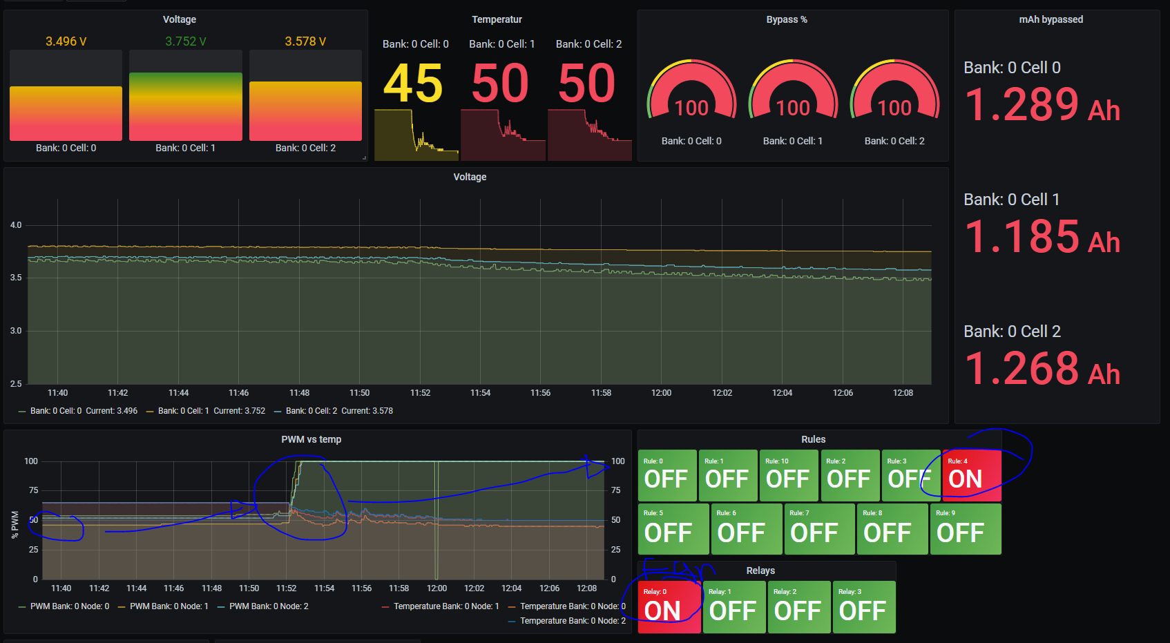
Doing dashboards in grafana isnt that complicated and earlier in this thread i posted an image of it
Does anyone have any recommendations for a reasonable latching relay or contactor to disconnect the battery using the diybms relay? For a 48v battery and maybe 100amp+
@garethb If you goal is to have a good disconnect breaker in terms of fault = you disconnect and you dont engage again. I would recommend scavenge a 2nd hand ABB s3 breaker in your case. You can get them between 100-300A and they are basically made to deal with over current as well. Just get one with a DC shunt trip attached. They cost around 50-90 USD if you ask me.
If you talk about contactors/relays so that the system can engage it again when fault is over? Then you have large contactors for the 12v market around. Though havent tested them.
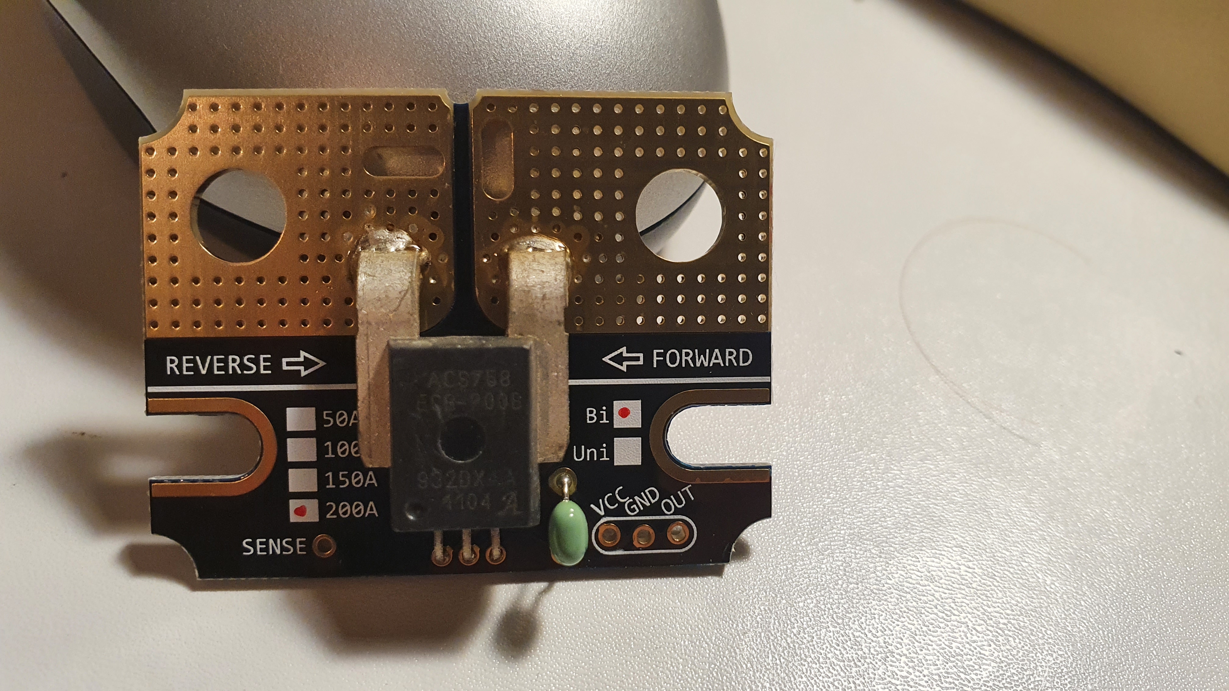
Doing some quick tests. Testing capabilities of balancng on current setup. Without cooling and with ambient of 22c+ you get a duty off around 50% (its actually less in real world but will show the numbers later). And with a rule triggering cooling you can sustain 100% without issues.
Daniel, have you tried any heatsink options on the DIYBMS modules for better cooling?
I’ve also wondered about using aluminium PCB’s instead of glass fibre.
Thanks! I would like some more info on it like A(both directions), soc, rules or relay channels like Daniel below this shows.
Retention is no issue, i run influxdb on a virtuele machine on my server, it has plenty of room.
3 weeks or a month retentions, is enough, so that when i can go abroad again a can look back and analyse.
Stuart: Havent tried passive cooling yet but i have heatsinks on the bench for it and you could use conformal coating with heat dissipating capabilitites. The later could also be protection towards moisture if needed.
If you want to sustain 100% colling based on the resistors some kind of added capability to cool is needed.
@daromer that looks exactly what I want! Thanks! So would you recommend I connect it to half the battery pack to give it the 24v it needs for power or an external power source? Would this cause much draw from the half that’s connected and cause the cells to become unbalanced? Or is the power draw so minimal it won’t make much difference?
Also, the standard Arduino relay boards give enough current to trip the breaker?