Did you just download the zip file or did you install GitHub? Platform Io is reporting an error as it can’t find the git tool.
Yes all the bits you need except for cables between the modules.
I downloaded the .zip file. In ‘latest releases’
Opened the workspace and it doesn’t work.
When I clone the master it works, but not with the new web interface. (version number and relay rules)
Hey fellaz,
Thanks for your help / info about the data that gets sent to influxdb.
Now, Grafana, InfluxdDB, and MQQT is all very new to me. So far I have done a bunch of research and whatnot, and was able to get Grafana installed on a Raspberry Pi including InfluxDB for the database. And the other day I was able to see two different data inputs from the DIYBMS in the InfluxDB database. Not exactly sure why I didn’t see the rest of them but I will check again tonight and see what I can figure out.
But in your latest reply you mentioned that all those different values are being sent from the DIYBMS thru MQTT… Are these values also being sent to/with InfluxDB?
From a few different tutorials when I set up the Raspberry Pi with Grafana and InfluxDB it seems as if MQTT “or” InfluxDB could be used as a database…
In the DIYBMS settings, there are both MQTT and InfluxDB. At the moment I only filled out the information for InfluxDB. Do I also need to fill out the MQTT info as well and get MQTT installed on the Raspberry Pi? Or do I just use one of the other? I was under the assumption that either MQTT or InfluxDB can be used as a database to get info into Grafana.
Thanks again. And please bare with me on this just for a little while until I can grasp how Grafana, etc All works.
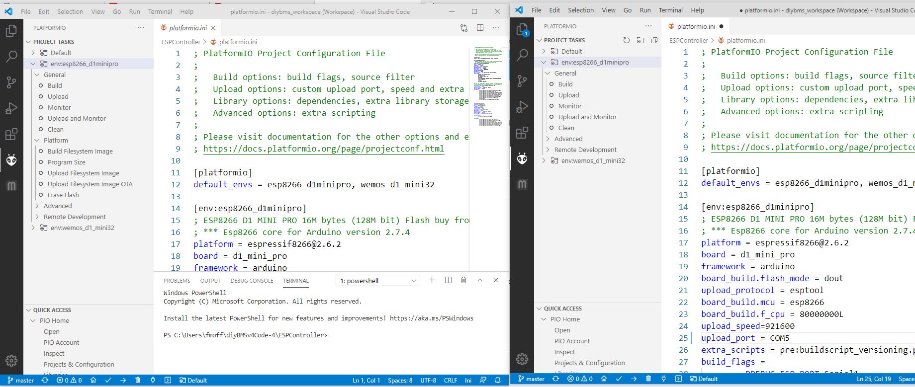
Hi Fred, please use the YouTube video I made to show you how to build the code. The releases version of the code isn’t the latest one.
Thanks for responding.
Watched the video
Cloned repo…Opened workspace…changed com port and clicked ‘alien’…clicked upload (success)…looking for ‘Upload File System image’…looking…looking…looking…
This issue just doesn’t seem to go away for me.
There is no ‘Upload File System image’.
Oh, It moved under ‘PlatformIO’ ok.
Wait, now there is no ‘PlatformIO’. now where is it?
Is the software updated? Is the version too new, too old?
Have you cloned the repository? Have you downloaded the .zip file?
If you downloaded the .zip file, oh it won’t work…why have it then?
With every new update I’m beginning to get ptsd
Great Project Stuart, don’t get me wrong.
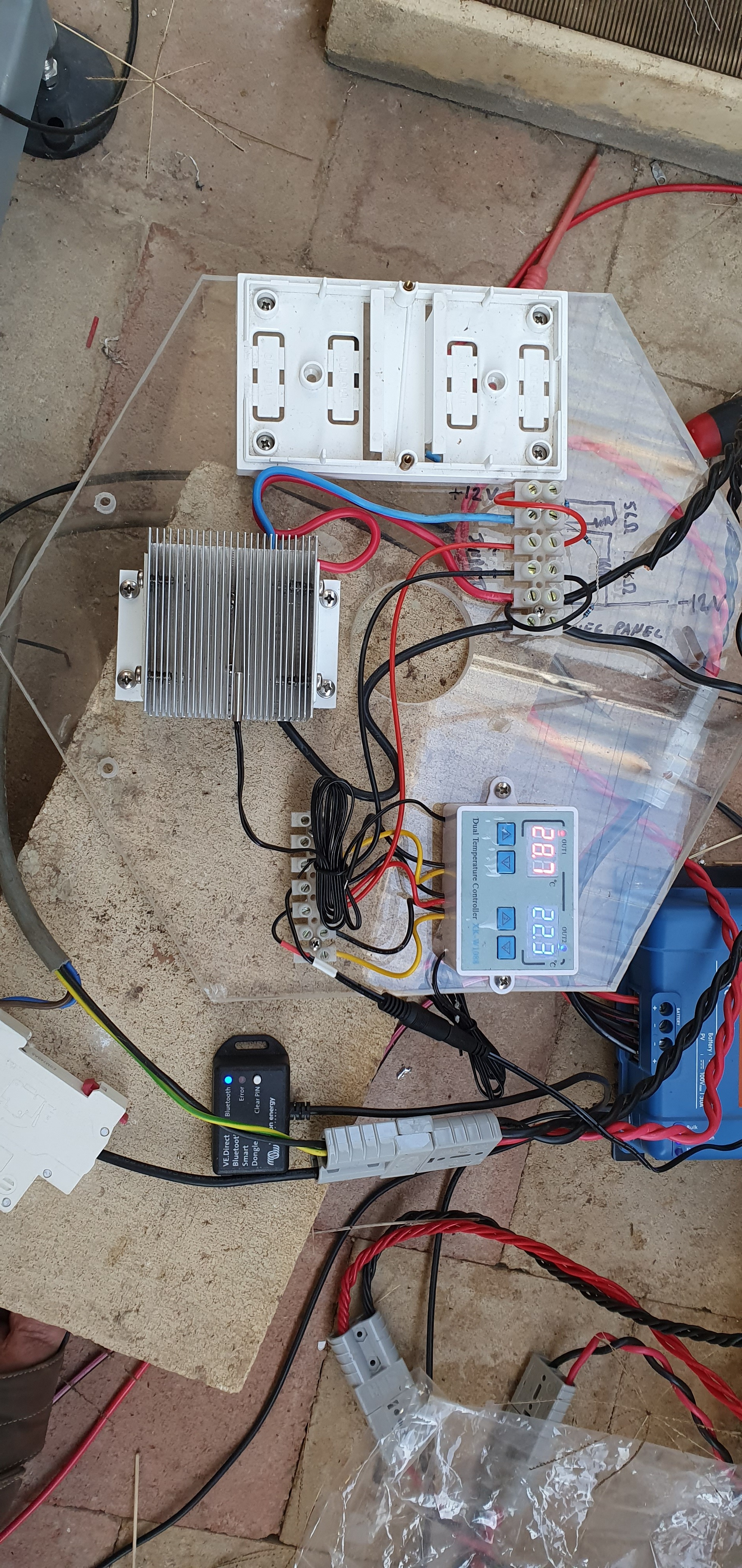
A little off topic but related, I have been playing around with DC switching high current, high DC voltage using Mosfet to do the switching, with a 5v source like the relays used in the diyBMS I would like to power down or up a battery or solar controller PV inputs, so far it is looking possible to use a mosfet instead of a relay that has limited capacity
Interesting but why do you want to use this and not a DC breaker with shunt coil ? I mean the FET’s are not that cheap as i can see. Is it because you also want to turn them back on programatically instead of manually which is the case with shunt trip coils ?
This may help…
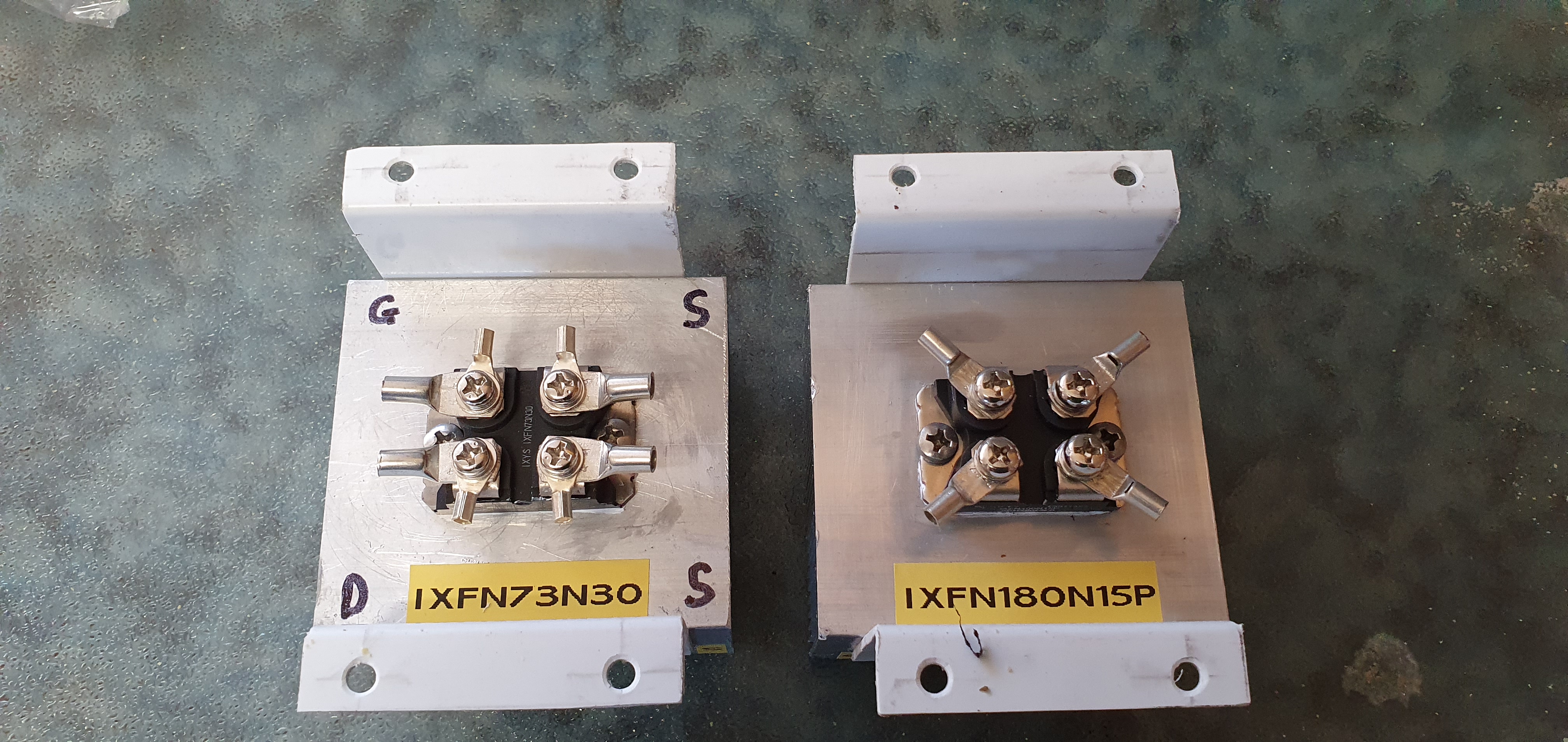
The mosfet are solid state and cost me about $40 each not including a heatsink, there is no contacts to get fused together or burn out and with no coil to heat up, and needing very little energy to run, I find that there are more pluses then minus, and can handle large currents continuously
I guess this could also be used for battery ? The contracts seem small but I see they are rated for high current so they must handle I guess. The battery terminals are quite big in my case. So how do they work in practice. They stay open when there is 5v ? Do they use power when they are open eg turned on or when they are off ? How much do you think in total cost you end up ? I can see you use Victron equipment, so do I.
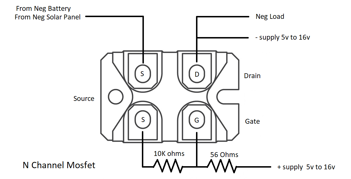
The N channel mosfets needs switching voltage to turn on the circuit, and as i have not work on P channel mosfets but I think they need switching voltage to turn them off.
This is only experimental at the moment and not tested fully, so be wary as i am not a electrical expert and far from being one, but the layout is as shown.
Depending on the circuit voltage, one concern might be RDSon, i.e. the voltage dropped across the FET when turned on and passing the full current. You need the heatsink for a reason - it’s to dissipate the power that arises from that voltage drop, and that power is effectively going to waste.
Yeah i was wondering that too, heatsinks are there for a reason to dissipate i saw some extremely hight numbers in the datasheet. Power Dissipation (Max) 680W (Tc) !!!
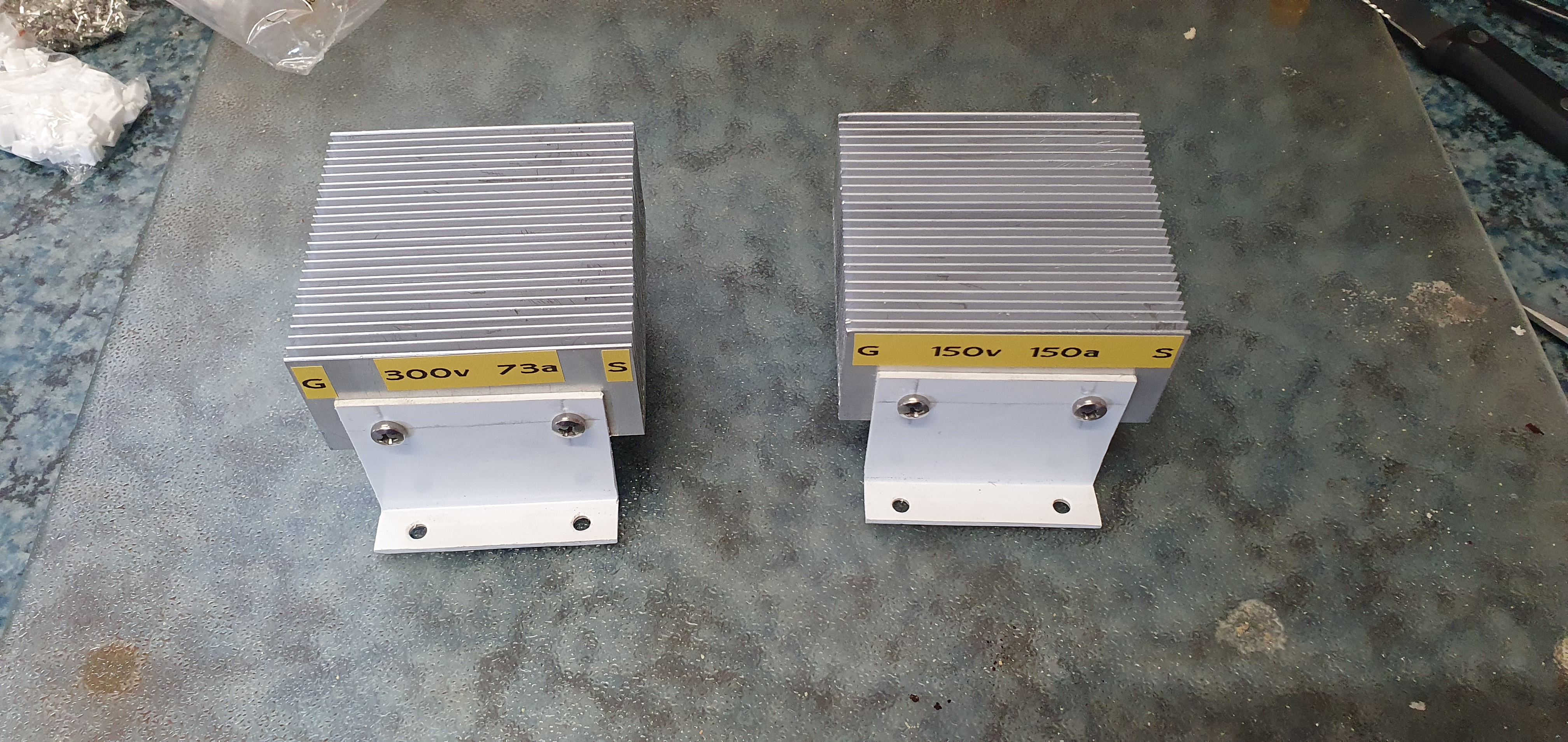
One mosfet is 11m ohms and the other is 45m ohms RDSon, yes heatsinks are very important, that is why i have made bolt on plastic angle mounts so the mosfet mounts on the bottom of the finned heatsink and not the top, as heat rises. will keep informed under load condition
The best mounting arrangement will be to bolt your brackets to a vertical surface, so that the base of the fins, as well as the fins themselves, is vertical. That way you will have a clear convection flow of air across the full depth of the fins.
Damn… The smallest thing has been driving me crazy for 3days now.
I couldn’t figure out how to reset the esp8266’s saved wifi credentials that I had Initially set. So I had flashed a new esp8266 with the same Diybms v4 code as the first one…
But now when I power it up and connect to its ssid that it’s broadcasting and try to goto 192.168.4.1 the browser seems like it’s trying to connect and then fails with error 500. So it can see that the address is there but cannot connect to it.
And if I run a ip scanner or various commands on the command line it all shows that 192.168.4.1 is there an available…
I tried everything I can think of. Including different PCS and my Android phone, as well as another brand new esp8266.
Is there a way I can manually set which SSID and password it will connect to in vscode before I Flash the esp8266? Instead of having it broadcast it’s own SSID initially?
Or does anyone have any ideas what’s going on
I guess I’ll post this here as well.
I would think you would want to stay away from ‘magic’ or ‘magically happening’ in software development as well as in electronics.
Having the ‘Upload File System image’ magically appear in one window and not in the one immediately opened afterward be a flag.
I don’t understand it.