DIYBMS v4

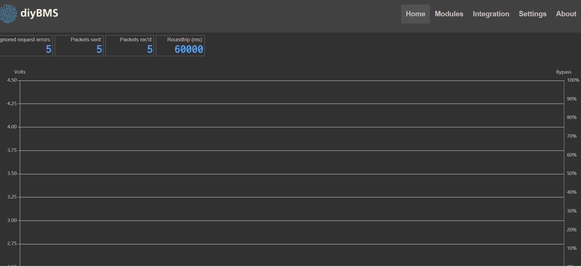
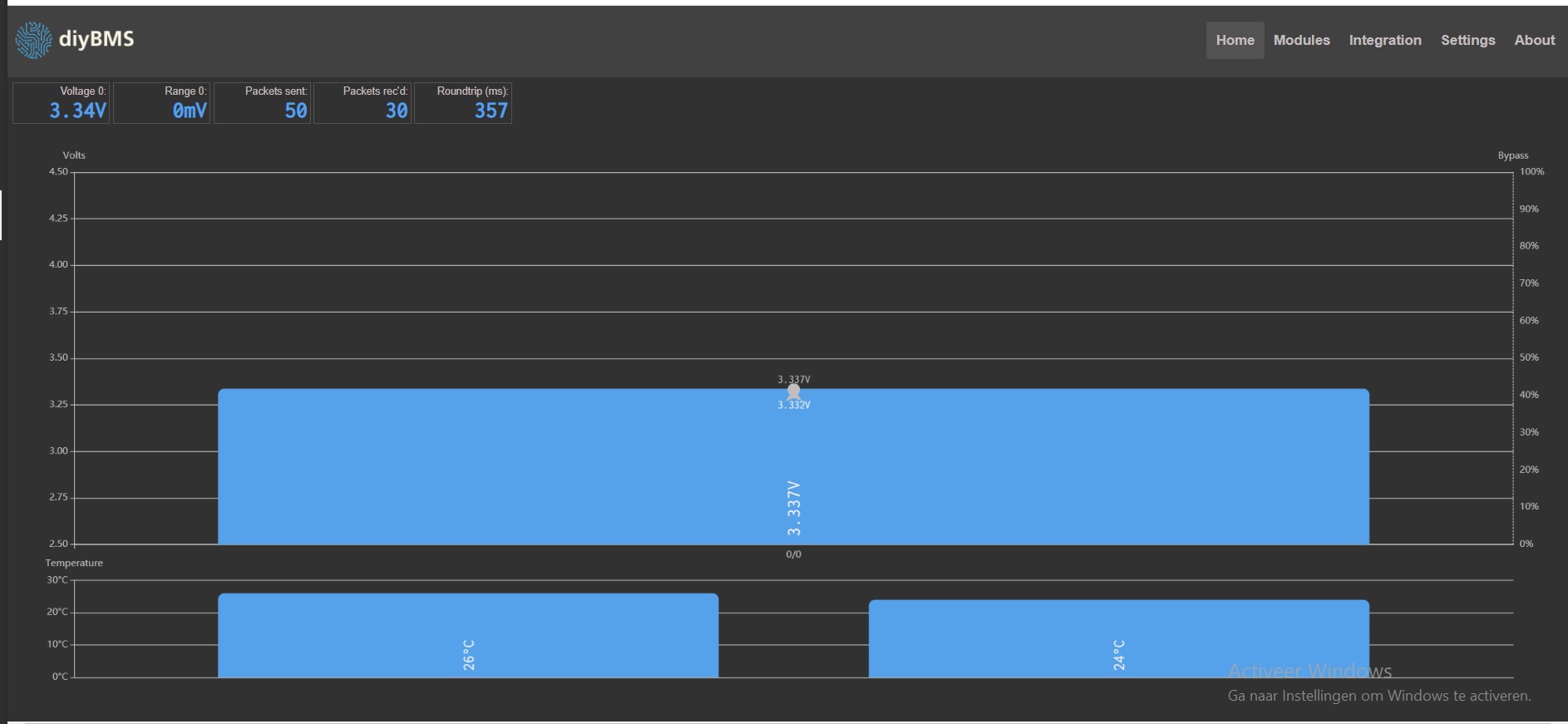
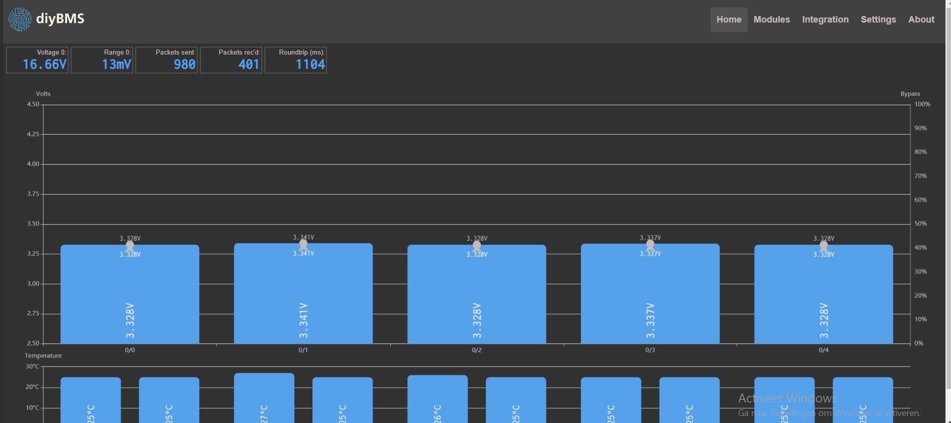
Thanks @stuart. So yes I measure close to the module with the voltmeter. I have one of those short leads (very thin gauge with the JST connector) where I then connect my lab supply with crocodile clips which cables are rather long I would say, around 50-60cm but the gauge is quite big so there shouldn’t be much voltage drop and I can confirm the voltage as I say since I measure 5cm close to the module and that voltage fluctuates very little 0.01 V where the reading on diyBMS is 0.09 V so its not much as you say it’s probably within range.

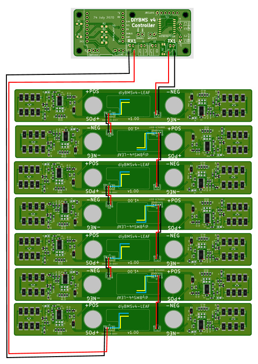
The cable for PWR are the small leads (very thin) mounted with JST plug, any recommendation on gauge for the PWR cables and also length wise ?

So the module will continue to be in bypass until the temperature is high then lower current and when temperature is lower again it will bypass again ? It will go thru this loop indefinitely until the voltage get’s within range. Is this correct understood ? The temperature it uses is that the bypass temperature or another temperature internally in the module ?

It would be nice to know about this to understand the workings about diyBMS so one know how to react and inspect when you use it.

Correct

I am totally missing the “platform” option you seem to have.

I’m using

VSCode…

Version: 1.50.1 (user setup)
Commit: d2e414d9e4239a252d1ab117bd7067f125afd80a
Date: 2020-10-13T15:06:15.712Z
Electron: 9.2.1
Chrome: 83.0.4103.122
Node.js: 12.14.1
V8: 8.3.110.13-electron.0
OS: Windows_NT x64 10.0.18362

Platform IO Core 5.0.2 and Home 3.3.1

If you click on the PlatformIO icon (alien head) and then “Platforms” - do you have “Atmel AVR” as an enabled platform?

image

Great - the controller is wired up correctly and all is good with that.

Now add a single module to the “controller tx” to “module rx” and “module tx” to “controller rx”

and hopefully it appears :slight_smile:

nope, and searching for atmel avr does not give me this as extention.
it does give “arduino” and after installing that extention it does show me.

screen 8
screen 9

sadly also provides me with an error:

screen 10

I googled on the Atmel AVR and visual code…
it seems that you need to install studio7 (874mb) to be able to use “Atmel AVR” ???

I hope not needed…
With my internet speeds (3G) that will take a day or more to download…
soletimes if the atmosphere is good, we have OK speeds.
one of the down sides of living remtote.

I’m affraid that this does require me to flash all my + 50 cell modules again… :frowning:

During initial flashing i didn’t get any errors.
Clean computer with no arduino history…
that apparently needs some more softrware installations then the video suggests…

but need:

Correct??

perhaps

being a Noob for arduino have its benefits to be taken by the hand by your experts…
sadly for you… it means a step by step guide noob proof :slight_smile:

Don’t worry, i’ll help you to get the gaps in the open :slight_smile:

I don’t have atmel studio installed.

If the ATTINY/module code compiles okay, then it must have the necessary files installed.

Don’t worry about it, try connecting a module to the controller and see what happens.

this is the part ive done several times, no change :frowning:
it simply doesnt see the cell mudules, while it seems to be communicating with the pcb…

placing the tx direct on the rx does give the errors, adding cell module just shows what i have seen long enough…

I installed the adruino extension for visual studio, after this I got the “platform” and ability to set fuses.

Tomorrow I’ll flash a few cell PCB’s with the new installation and set fuses after programming.

Any tips on how to erase the old information?
Or is “upload” enough?

Thank you all so much for supporting!!!

My best guess now is that the original flashing didn’t went OK due missing adruino extension.

If it still doesn’t work, I’ll try the standard adruino suite installation (125mb) and otherwise the studio7.

Good time to restart the downloads…
And get some sleep :slight_smile:

I need some help. I am very new to these topics. I have been able to mount diybms on leaf batteries, but I cannot communicate and the LEDs blink blue. Before checking all the wiring, I need to know if I have done it correctly, can someone confirm me?
The plates are assembled by JLCPCB and by the openenergymonitor store (controller), with which I discard bad welded.


Can anybody help me?
Thank you.

1 Like

Welcome, @manuromero05

Your post was blocked by the system because it appears you wrote it and then copied it into the forum. If you use the editor here and type directly into the page, it should be OK.

Okay @fhorst1

Lets get 1 module working…

From the TX on the controller board connect this to the RX of a module - first connect it on a pin 1 to pin 1 and pin 2 to pin 2 basis. Don’t worry about connecting the TX from the module to the controller for now.

If that works, the LED should flash green every 4 or 5 seconds.

If it doesn’t, connect TX pin 1 to RX pin 2 and TX pin 2 to RX pin 1 (swap pins over).

If that works, the LED should flash green every 4 or 5 seconds.

@manuromero05 I think you have the same issue as above - just try swapping the pins of the connector TX on the controller and see if that kicks everything into life.

1 Like

The green flashing is OKAY… and…
the magic happened!!!

What is totally strange, as it seems to me exactly the same as before…

Except for the “creating ignored errors” by contacting Tx with RX directly.
(and now using a random board, all components, including attiny841 soldered by jlcpcb)

Hard to wrap my head arround it…
understanding why it sudenly works…

I’m happy that it does!!!

I just did my second controller board, with different wemos.

at start exactly the same nothing.

creatin gthe errror by contacting Tx with Rx, and then connect the cell modules…
tada…

that really does the trick for me!!!

I was planning to setup my 3 x 16 cels (actually 2x32 and 1 x16) using 3 controller boards, and placing the relay boards output in series.

if one of the relays decides on a disconnect of the contactors, it will brake the chain.
for things to turn on, like a fan, it goes in parallel.

it can do something as “banks”
i tried to play with it, and i can move 1 cell to diffrent bank, but only 1 cell??
perhaps some setting wrong.

is there a benefit for using this?
(when i have 3 controller boards availible)

can i use MQQT to see al 3 x 16 cell PCB’s in one installation?
or is it better to use 3 x different IP adresses

0.07 AM… i really need to get back to bed…
(Thailand GMT+7)

If you are running 3x16 cells (as one pack) then a single controller board will run and operate that.

You set the number of banks to 3, and then move the modules (one by one) to a different bank.

The rules then apply to the whole bank/pack and you only need 1 relay board as well.

1 Like

thank you for explaining.

I do have 5 controller boards and 5 x relay / wemos.
I like redundency :slight_smile:

After troubleshooting part one… we move on to part 2.
All my 3 controller boards have the message:
"PCF8574 is NOT fitted, relay control not possible!"

I assumed that this was a message as I didn’t connect a relay board…
cheered to soon… When I connect the relay board… the message stays.

I know I’m not high class soldering, under a microscope all pinns / legs seem to connect just fine.
They didn’t get too hot, not did I touch them with my hands…

All I can think of is orientation, but that would be strange…
the while lines on the pcb are quite clear where the notch should be (towards the 6 pin header)
I don’t think my soldering skills are that bad :slight_smile:

Probably due using the WRONG Gerber file…
Yes, noob at making PCB via github and JLCPCB…
I used the gerber from the Master…
https://github.com/stuartpittaway/diyBMSv4/tree/master/ESPControllerCircuit/Gerber
and could not figure out how to do the BOM / CPL… (could not find them)

I think many of the problems will be fixed by ordering 5 new controller boards…
For $28.22 (I had coupon for $8) most problems probably will be solved :wink:

@stuart, can you please add dummy file in the master directory (and subs) with the name “NOT FOR JLCPCB, use -diyBMSv4 - jlcpcbassembly” ???

Your video wasn’t released yet when i did my orderring, and after watching, I saw what I was doing wrong.
I just didn’t expect that the master gerber would be outdated… (or perhaps even wrong)
controller boards will arrive in 2 weeks or so, till then i just can continue to build my battery array, and prepare for the new controller boards.

the old ones just stay buggy :slight_smile:

@fhorst1 you are far to keen to throw more money at the problem!!

To fix this, simply change the value in file main.cpp using VSCode (this is for the controller).

There are already comments in the code indicating what to do if you have a different variant of the PCF chip. Change the 0x38 to 0x20 and reupload to the control board, problem solved :slight_smile:

//PCF8574P has an i2c address of 0x38 instead of the normal 0x20
PCF857x pcf8574(0x38, &Wire);
1 Like

Nothing wrong with the controller Gerber from master - only the LED component has changed between that and the JLC branch.

The module on the other hand is significantly different.

Perhaps…

It’s not just the PCF chip.

The need for resetting the communication by connect Rx with TX isn’t giving me much faith in the reliability of the boards I made.

After several hours (a night) the same trick needs to be done again…

Something that can be scheduled with a relay to reset several times a day…

But that’s not a good solution.

If “others” have no problems with their controller boards, and mine gives several, spending $ 30,- is a small price to pay over the sleepless nights and hours and hours of troubleshooting.

If you know what you are doing, sure…
Easy fix.
And in a few years I might laugh about it.

Walking “blind” unknown routes without constant guiding and knowing it takes weeks to get any small part, if there is need for any replacement…

Walking the known path that works for “everyone” is the best route for me now.

I’ve spend several hundreds of dollars on BMS that all fail, or are unusable.
(Need to pre-charge my inverters before the BMS can start)

Dumbo and “smart”…
China crap.
Known brands like “Daly” are totally junk above 100A

With my 50kwh LiFePO4 I use tops of 250-300A.

Anyone interested in a Daly smart 150A??
:wink:
Will work lovely on small system, but not for me.
Even have display, Bluetooth, UART SOC led indicator and can Balance magnificent 35mA…
Lol.
Eating dust.
135 days without BMS , except me monitoring to prevent too high charge…

Not so fun.

Lucky I have active Balancer that have Bluetooth that gives me quickly overview of the cells.

“Permanent” solution is more then welcome!
In that aspect… $ 30,- is “peanuts”.
(Not for my wallet)