Thanks, I just check my datasheets and the operating temperature is -40 to 120 which is the same as those on the PCB, only reason I am opting for mine as they are the only ones available here, and based on the datasheet only the B value is different and I’m not sure what impact that has?
Hi
Can I ask about DIYBMS website monitoring?
I noticed that when “Ignored request errors” change, bank 0’s Vmin and Vmax values reset but bank 1 does not reset.
@stuart can you confirm if this will be ok for a pack thermistor
THERMISTOR NTC 47K 5% B=3900K
The temperature rangers are the same only difference is the B values
They should be ok, you will need to change the B value on each module via the configuration.
I’ve not tested that explicit device though so buyer beware!
I’m not at home right now to check the code to see what’s going on there. You shouldn’t be getting any ignored request errors though!
thanks, they are pennies but all I am able to get locally
The BMS already has a pulsed output on the relays, it’s about 200ms.
Not so, thermistors are given a rating at a standard temperature of 25oC.
No don’t do this, you would short circuit your battery and possibly cause fire or worse.
If you are interested in this sort of thing search for active balancing, but diybms doesn’t support this.
I’ve had an idea for the modules. Could we use the extra outputs to drive a external bigger mosfet and dump load, when say the internal balance resistors cannot cope but before the controller switches off the charge controller via relay.
For example the internal resistors switch on at 3.9v, bigger dump at 4.0v, then controller switches relay at 4.1v to turn off charger.
I also have a circuit that I’d like to try which would actually add active balancing to the modules. It works by boosting the voltage of a cell that is high up to pack voltage then injecting it back into the pack.
Having another pin do this allows the balance resistors to still balance in case of a fault.
Do you actually need this though?
From experience, most larger power walls are well balanced to begin with so require little help from the module balance.
Additionally, when the cells are near maximum voltage the charge current will drop a lot, this should be designed to be below the maximum balance current of the modules, probably around 10A for a 14S battery as an example (current is shared across the cells)
Maybe
I have 25S in series for 70-90V it’s too many module.
Module 0-12 of bank0 has little Bad package count (0-4 count).
But Module13bank0-8bank1 has much more Bad package count (10-22 count).
After run 2 days.
This is generally true if you are using new cells to begin with, but i myself am using reclaimed cells. Also this would be handy if a cell has to be replaced, Allowing quick balancing and quick commissioning of the pack.
Current is the same at all points in a series circuit.
I wouldnt even want pwm, just on or off based on a set voltage of the users choice. This could be configured to come on before or after the internal resistors.
It doesn’t even need to be used for balancing, a small fan, a led to warn that a cell has gone above a set voltage.
Basic electrical/electronics theory, I know, but for the benefit of those who may not be familiar
with said theory:
Current is the same at all points in a series circuit.
Parallel circuit, that’s another story.
Hey all. New member here. Thanks Stuart and the community to making is project a reality.
I’m not yet an expert in electronics and as a software developer I sometimes questions assumptions. Why we need so many BMS boards? Seems like BMS per cell is a waste of resources, no?
Correct me if I’m wrong but balancing algorithm finds 2 cells - one with min voltage and one with max and try to balance them to median between two.
Can we just have 1 or 2 BMSes and loop the whole pack and balance those sequentially?
in that case we will need 2 BMSes tops for any size pack. It may take longer for large packs though.
Just a though. What do you guys think?
Thanks in advance
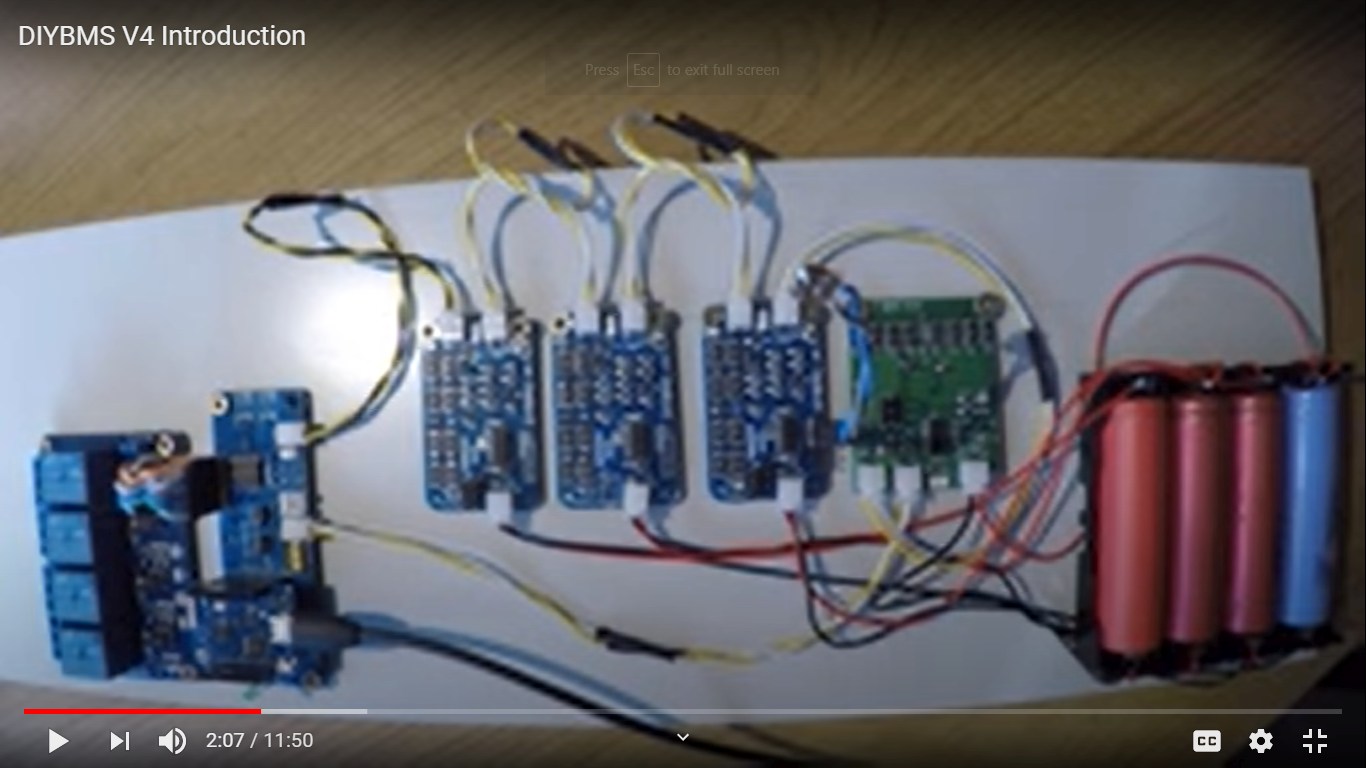
Well after a very long time I have finally got my 1st bank hooked up, just want to say thanks to all that helped here and especially to @stuart


Powerwall with DiyBMS operational

Thermal Video of a module in bypass

It looks like HBpowerwall-design wall mount was specifically designed for DIYBMSv4 boards =)
Nice place found to mount the boards - looks awesome!
Great thermal video, how accurate was the temperature compared to the BMS reading?
so the BMS is set to 65 deg, and if you look at the thermal video it gets to 64 deg and then cools off, so by my book that’s as good as perfect