DIYBMS v4

:slight_smile:
I only mention that I like to use headless bolts.

Funny thing about them:
I can’t find them in copper, brass or aluminium!!
Iron threaded rods can be found to cut to lengths
Or 304/carbon steel.

There will be connection between aluminium and copper, with possible some galvanic corrosion issues.
Unless all copper or all aluminium solution.

I choose copper bar to make the bus-bar.
For the weak spot, the 6mm threads, Yes, better not take chances on galvanic corrosion.
It will be a pain to repair if it would eat away the thread in a few years!!

But good thinking!!
Using copper bolts (headless or not) into the aluminium terminals with shallow 6mm deep thread will eat away the thread in years time.
304 doesn’t give any problems
Carbon and normal iron will desolve as rod, not the terminal.
Good Powerwall can last a decade or longer.

Things like galvanic corrosion are important factor to consider.

Just a reminder for anyone placing a JLC PCB order, you can use my discount code for a few $$ off.

Code:
JLC-Stuart

2 Likes

These are two of what the electrical industry uses to prevent oxidation/corrosion between dissimilar metal
conductors. I can’t speak to global product availability, rather these are examples of an inexpensive answer to the question posed.

This stuff is good. To the point that ā€œif you can see it, you’ve applied enough to do the job.ā€

https://www.amazon.com/Burndy-P8A-Oxide-Inhibiting-Compounds-Container/dp/B008KLX2RY

1 Like

Bit off topic, but has anyone played with mosfets for switching high current DC instead of solid state relays, I have not had good run out of solid state relays, would be nice to buy a straight off the shelf mosfet board that would switch the main battery current off with the 5v relay board that run on the diyBMS.

Yes, at other forum (diysolarforum) one of the members build SSR with mosfets.
(As that is what SSR is, mosfets)

I don’t like SSR for the reason they get hot and use magnetic contractors aka relays.
Yes they use more electricity, 400A is about 11 watt during connection and 3 watts to hold it.
And that is crappy China brand…
ā€œReal oneā€ (+/- $120) are more energy efficient. (On Mouser. Com or other site)

Really complicated material to do it right.
And a good build SSR doesn’t get hot!!
Problem is the price of the components…
So they don’t build :frowning:
They built crappy ones that do get hot.

Normal usage for SSR is many connections for a short time.
Normal usage for contactor is one time contact for long time.

If you like to get in contact with him, send me PM in that forum.

I’m easy to find…
Or just search for solder paste to improve conductivity :slight_smile:

Back to that, yes I received the tip of antioxidant.
Hard to find here! Perhaps I can determine active component and go from there.

Other is di-electric grease silicone based or petroleum based.

Somehow that sounds counter productive.
Remove the oxidation as it’s not conducive and then put on non conductive paste…

I understand the usage for lightbulb or plugs, it’s not good for interconnect copper to copper bus-bar.

Probably just cleaning, remove oxidation, and use rubbing alcohol to remove possible finger prints will give optimal contact between the 2 copper bus-bar.
Nothing else, just flat copper to copper compressed together.

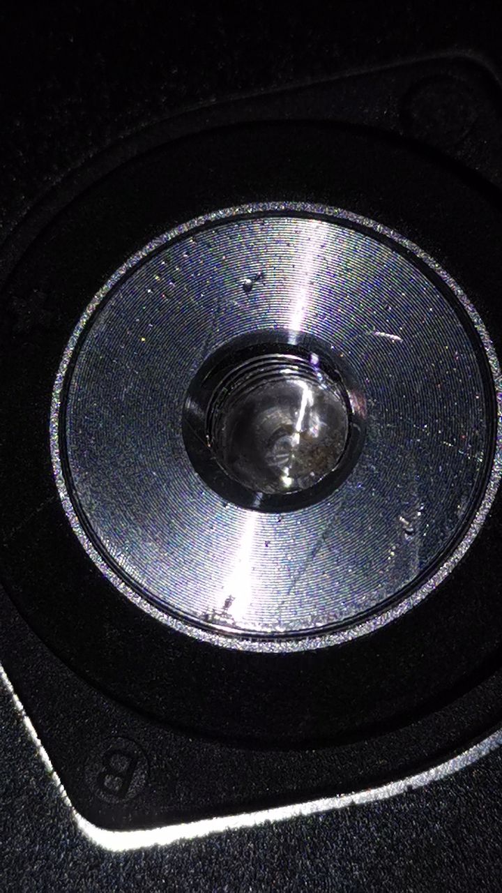
For the aluminium terminals, adding thin layer of silver hi-conductive paste makes sense.
To prevent galvanic corrosion and even out the bumps of the terminal.
(Bumps, if you zoom or have good monitor you see the circles in the terminal. Not totally flat)

Adding solder paste between the copper bus-bars won’t improve.

The anti-oxidation products can help, if they are available.
For sure they will make the copper look longer nice :slight_smile:
Cheapest I can find that will arrive in a week is + 100usd…
No local available products.
For this type of stuff Thailand really sucks.
For the rest, life is great here.
Just don’t want the fancy complex stuff and you are fine.
Any household solutions??

Cleaning oxidation will go perfectly with lemon juice and baking soda :slight_smile:
Those are available :yum:

@stuart, do you hear something from the mice :mouse: ?

you could use aluminum foil

You can only use it once though.

Hello Stuart.

I just thought about adding a set of V4 to the V2.
I want to build.

Now I came across the two branches in the Github (master and jlcpcbassembly). Are the versions as far as both technically and functionally the same except for the positions of the components. Or is there information about the branches that I haven’t seen.

Second, I would be interested in whether I can also get 1206 SMD on the board (I still have tons of parts here, but all only 1206 and 1210) or only fit the 0805 and 0603. Unfortunately, I am not so fit with KICad, otherwise I would already have it given and checked whether 1206 and 1210 would fit.

Thanks for information.
Have a nice day and stay healthy.

I can report that I managed to compile the code and flash both the Wemos D1 mini and an attiny884 successfully in Ubuntu 18.04. I used Platformio. No special tricks required, I changed the platformio.ini file a bit but I’m not sure if that was needed in the end (tried to flash the ESP bin file to the Wemos :blush:)

Could not find a reference to Ubuntu in this thread, so thought it was nice to let folks know.

True, many of them are MOSFETs. Many are not. Some are not FETs at all, rather they’re bipolar
transistors, i.e a Darlington pair.

For most DC SSR’s the solid state switching device commonly used are power transistors, Darlington’s and MOSFETs , whereas for an AC SSR, the switching device is either a triac or back-to-back thyristors.

Ref:
https://www.electronics-tutorials.ws/power/solid-state-relay.html

1 Like

In a way it does, but the anti-oxidation compound won’t eat away and physically destroy a metallic object
the way corrosion eventually will.

1 Like

Can anyone comment of wether these thermistors would work for pack temperatures ?

THERMISTOR NTC AXIAL 47K 5%
AXIAL, GLASS ENCAPSULATED THERMISTOR,
NTC, 47K OHMS, 5% 3900K

I’m sure you are absolutely right.
Also absolutely positive that it’s far beyond my knowledge of electronics.

I just wrote something that was explained to me by electronics wizard, in my own words.

Doesn’t change the fact that SSR’s are intended to make many, many, absurd a lot of contacts in a short time.
While contactors / relays (some people call them contactor, others relays) are intended to make one contact for longer time.
Yes, it can do so 10.000 and more times, SSR is like 10.000.000…

I hope my battery array never reach 1000 connects.
During setup like 10-20 time and then ā€œneverā€ :slight_smile:
Just keep on working, and just for safety being able to disconnect when needed.

That is totally outside the intention of SSR…
They supposed to do thousands connections per day.

In dept knowledge…
Nope.
I am intelligent enough to learn if needed, at 52yr I spend my time on different things.
Like Living off grid life in Thailand :slight_smile:
And building successful the DIYBMS.
The guide of Stuart was really helpful.

You so need to install some git repository stuff I was not aware off.

I wrote it in the comments section of that video of you have clean computer and nothing for this work yet.

Thanks guys!!

I’ll end up using silver conductive paste on the aluminium terminals.
To increase contact/conductivity and avoid galvanic corrosion.
For the copper to copper bus-bar, I have some di-electric grease.
Copper that doesn’t get contact (the space between cells, I probably treat the visual side with the same di-electric grease, untill I run out.
After that, vaseline is good alternative.

I also do have a shitload of shrink-wrap…
Perhaps good to use it for this.
It does give some form of protection in case of error (like accedently dropping something on top of the setup)

Things will be beautiful when finished :slight_smile:

A relay is for small currents, a contactor for large currents. There is no strict dividing line between the two. Power Relay is a term also used for a relay that is getting close to a contactor in current/size.

The big advantage of a relay/contactor over a solid state device is the voltage drop - millivolts for a contact in good condition, whereas a SSD can be hundreds of millivolts.

1 Like

with the modules would it be possible to run a relay from them instead of burning off excess power through resistors but to actively relocate the power somewhere else ? or some other form of power gate

ie )if cell voltage is low the relay is off (NO)
if cell voltage is high the relay is on (NO)

then these relays could connect to a balance wire to redirect voltage to low cells from the high cells ?

@MasterCATZ a system like that is called ā€œactive balancingā€.
And no.
Controller can do 4 relays
2 you need for too high/low
The 2 others you might be able to use like this for the total battery pack.

If you like per cell, each cell need its own relay…
And then a system to slowly (not maximal discharge possible) discharge the highest cell at 0.5C (or different, depending on the product) and transport it to the lowest cell via buffer (cells can’t be in direct contact)
That extra charge needs to be restricted as well.
You probably are charging at that time, so are already feeding the lowest cell.
Safe would be to feed it with 0.05 or 0.1C for 0.5C battery.
Again, depending on the rest of the setup.

It isn’t that easy :slight_smile:

There are commercially available active balancers several that won’t work.
A few that work and are relatively cheap
But start at 0.2V difference.
Expensive one ($75, 1A) that works 24/7 up to 0.004 cell difference.

I have the expensive one from ā€œicgogogoā€ (AliExpress) it works slow but really works.

I bought the cheap one ($22.50 max 1.2A) for different setup.
(Both S16)

From the expensive type, they go up to 8A.
For my 50 kWh 1016Ah Powerwall the 1A is sufficient.

A really large installation or one with ā€œdubiousā€ cells can benefit from that big boy.

This are the specifications of the thermistor on the PCB, and they work also for external sensor.
(Just solder 2 wires)

The ones you like to use have different specifications. They seem to be intended for much higher temperatures.
Most likely not accurate enough at the temperature range needed.
It seems they have minimal temperature of 25 Celcius.

2 Likes

Yes, the silk screen was off in the pcb so I’ve tried again!