Hi all. I was wondering if there is any general documentation or FAQs on the features, functions and specifications of diyBMS available anywhere?
Some general questions I’m looking to answer are:
What are the high level functions/features of diyBMS and how, in a general sense, does it achieve those functions.
What are the specs and limits of the product? Amperages, etc.
Some specific questions I have are…
When charging/discharging a battery bank, is the current passed through diyBMS like it is on some other BMSs? Should a charger be hooked directly to the battery?
What are the limits of the battery balancing capabilities?
What is the quiescent power requirement of diyBMS?
I see mention of external temp sensors. Is there a thermistor (assuming it’s a thermistor) part number that’s recommended?
Those are the types of questions I have. I’ve tried scanning through the thousands of posts, but it’s a little unwieldy and I was curious if a central depository for information like this exists.
I’m away on holiday at the moment so this is just a quick reply.
The diybms doesn’t channel the current through the BMS, this gives you the flexibility to have as little or large current as you need. The BMS can control relays or contactors to handle load and charging.
At the moment the biggest shortfall is the lack of current monitoring. This is coming soon, and some users have already implemented a basic implementation.
The BMS itself uses very little power, the modules use micro amps/h and are powered directly from each cell.
The controller uses more power, but still tens of milliamps.
I love the idea of this product. Being new to all of this im curious if there is a video out there on implementing the BMS. Ive seen videos on building and programming. But cant find any thing on setting them up on a battery bank, setting overcharge, setting low voltage, etc. If that video does exist, a link would be most helpful.
It has a controller with a web ui, to monitor your powerwall, the controller can activate relays for the purpose of safety like shunt trips for over and under volt protection for the bank or individual cell packs or turning on fans ect… The controller can also send to MQTT and to Influxdb it’s data. In the works is a Shunt for measuring current pull or push to the bank.
Modules are attached to each cell pack and monitor the cell packs, their main purpose is to top balance at about 850ma, the can also take an external thermistor to monitor the cell pack temperatures. These obviously feed back the data to the controller
Currently is supports upto 4 banks and 64 modules.
Thank you for the reply. And while i understand what you are describing, actually seeing how its done would be great. Ive seen videos of guys install the the controller and modules and how to wire them together. But nothing on over voltage/under voltage protection, fans, or usage/setup of the temp sensors.
I’ve added a page for mounting options. I couldn’t find the link for the zip tie pad or the other pad with the push fit post in the center but I remember them being posted in here somewhere (not able to find it via search easily).
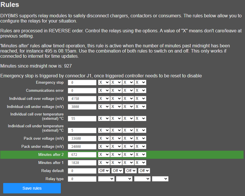
Below is a screen grab of the rules page, very straight forward, to input your desired values and click save, Stuart does have a video of this as well below
Im referring to how u setup the components, not the config of the software.
For Ex:
I can hook up temp sensors - How do i do that?
I can hook up fans - How is that done?
I am trying to add an email notification (to send SMS messages) to the controller software. The email sender fails. I have made a simple sketch that works and also uses the AsyncWebServer to put up a web page like DIYBMS. I am trying to figure out what DIYBMS does that manages to wreck the ability to send email. I think I need to figure out how to get serial debug info.
How do I get Serial.print debug output to platformio? It shows non printing characters.
It seems that the modules are using the serial object somehow. It seems like the normal serial output is going to the modules and there is a debug serial output that requires a cable to the debug pins on the controller. Am I right? If so, why isn’t the normal serial debugging going to platformio and the modules use the a new channel?
I am using a clone 4m. How do I know if the code and files exceed the capacity?
Do you have to upload and also upload file system whenever a code change is made? How are these two laid out in EE? How are they avoiding the EE space for the settings?
Bypass mode is there to top balance your cells, e.g If to set your cells bypass to 4150 mah, during charging, say one of your cell pack are slightly unbalanced to the reset and reaches 4150 mah while the other are still at say 4050 mah, the module for that pack will go into bypass mode and burn off any capacity while that cell pack is still above 4150 mah, which will allow the other cells to eventually catch up.
In these power wall setup its imperative that your cell packs are always balance else you could end up damaging a pack or worse should it become over charged start a fire.
The modules have a sensor port on the pcb which you can attach a thermistor to and insert into the center of you pack to monitor pack temps, the controller has the ability to active currently upto 4 relays, so you could hook a fan up to one of those relays to activate a fan, all these features have been demonstrate in this thread and by multiple people on youtube
That is correct, it will not balance unless it is near capacity and charging. I don’t think there is a way to balance unless the cells are near the top or bottom of their capacity because the voltage curve is so flat in the middle.
With large cells, I don’t see how it will do much balancing at all. For LiFePo4, you’d set the threshold at say 3500mV, and the charge cut-off at 3550mV, so the highest cell will bleed a few mA between the time it exceeds 3500 and when the controller realizes it is above 3550 when charging is shut off.
I am answering this to make sure that I am not mistaken. Hopefully others will correct me if I am confused.
Each cell module can have an external temp sensor. You have to get the module, then read this thread to figure out what type of temp sensor to buy, then solder in the connector to the module(s). If you want to independently measure each cell, then each module will have a sensor.
You have to plug in a relay board (search this thread for what 4x relay module works) that will be controlled by the controller in order to turn on/off fans or charger or loads. But all of that is up to you. There are no videos for that, since it all depends on what fans, chargers, etc that you are going to control.
The controller is configured with the UI and it should be somewhat self explanatory once you get it up and running.