Hello all,
Found this project searching for full featured BMS solutions for a shipping container workshop. I’m nearing completion of my build - 30 boards and controller all built and programmed, and relay board in hand. I’ll be using 14 boards for a 14S Li-Ion system, mounted in a recycled server rack, and charged by 2700W of solar panels running through a Midnite Solar Classic 150. Now that I have my battery mostly built, my solar panels and charge controller figured out, and the BMS boards ready to go, I’m now researching power switching solutions since the diyBMS doesn’t handle this like most systems. My understanding is the correct setup is to use the relay to switch a normally open contactor. This seems to be a significant power draw over time. Is there a recommended model to use, or a better solution? I was looking at the Albright SW200A contactors to get started. Thanks!
Your calculations look okay, what is the highest/lowest voltage these cells can go down to?
Just a warning to others - don’t use lower value resistors unless you are using specialty battery chemistry.
Thats right, the BMS can’t control the power of large systems so a contactor is the right way to go. They do draw power to do this.
You may also be able to look at solid state relays, but it depends on what power you are looking to handle. These can also fail and get “stuck” on.
Lithium titanate lowest is @ 1.6 volts but will stick to 1.9 to 2.0 volts and full charging voltage is 2.8 volts
I was avoiding SSR’s for that reason, as well as expense for DC units. Short term I expect to draw less than 3000w @ 48V (~63A), but may add more inverters later. Does anyone have any recommendations for contactors, or does the SW200A seem to be a good fit for a 48v system? That’s the one part of the system I have absolutely no experience or knowledge of.
You might struggle with such a low voltage. The attiny technically works down to 1.8v but suspect you will run into Comms issues before that.
Have you tested it yet?
I have ordered 30 boards tonight so the test will come once they arrive and get them programmed
Hi, JCB dont have enough [C25344 6.2Ω(6R20) ±1% 1206 in stock, can any one tell me if i can swap them for [C247230 56.2Ω(56R2) ±1% 1206 or am i best to wait?
Thanks
56.2 ohms is a long way from a 6.2 ohm resistor, I am no expert but i think it is not even close.
C17970 5.6 ohms 1% 1206
C25345 6.8 ohms 1% 1206
Thanks ,
Scroll up a bit and this was discussed earlier this week.
Thanks stuart
From my experience such a sw200a contactor continously draws 30watt… a bistable one should do a better job…
Regards
Karl
Hey @stuart can you tell me if this will work for the battery pack thermistor
THERMISTOR NTC AXIAL 47K 5%
AXIAL, GLASS ENCAPSULATED THERMISTOR,
NTC, 47K OHMS, 5% 3900K
Good idea,
Here is a possible option - a latching relay with 3W coil
https://shop.gwl.eu/DC-Contactors/DC-Power-Latch-100A-Coil-48V.html
@stuart, concerning this subject: maybe it would be a good idea to make a “pulse” option for relay outputs (like, if rule is TRUE then relay is pulsed for x seconds)? And, actually, it is a one more piont on the subject of having more relays/outputs, since latching relay needs 2 signals.
Just wondering if anyone has had issues with the wifi connection while operating? I’ve had mine running for over a year. But recently, my wifi will not connect. The system is working as I can see the sync lights working. If I just connect the wemos, it works. If I connect the wemos to the board without any communication wires, it works. But as soon as I add the balance boards,it disconnects? I have tried uploading the code again and the same results. I was thinking my wemos was bad, but the testing confirmed it wasn’t. Any thoughts? Also, I know it’s working because my cooling fan still works when the temp gets too high.
So an obvious note to everyone else out there, don’t connect the RX of the Controller to the RX of the Module it lets out the magic blue smoke from the D1 Mini… And seriously don’t do it a second time to a second D1 Mini coz you were not convinced the first time its just not cool 
Question not strictly DIY BMS related.
It is related to the usage of the DIYBMS.
So much combined knowledge here I don’t want to miss the chance on asking.
For LiFePO4 higher Amperage cells you connect the terminals with bus-bars.
Bus-bars that are bolted onto the terminal.
I personally use headless bolts as they place less stress at he weak shallow aluminium thread (only 6mm deep and max 8Nm torque!!!)
Anyway, to improve connection between bus-bar and terminal they obviously need to be cleaned and flat as possible.
I read that professional installers use silver electricity conductive paste. Expensive stuff!!
Many people use nothing in between.
Would something simple as solder paste improve the connections between the terminal and bus-bars??
Solder paste flux is non-corrosive
Solder paste have about 50% solder.
Naturally, a really thin layer, just to maximize conductivity.
It won’t be as good as silver, but I think a lot better then nothing!
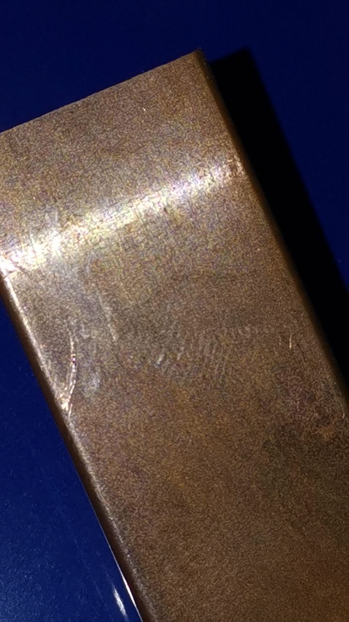
Both terminal and bus-bars (this is not yet bus-bar, now just copper bar) have minimal damages and the terminals have circles.
Flatening by filling the mini gaps should improve total contact surface, yes??
Or is it a dumb idea??
cheapest I know of is using Vaseline on aluminium electrical connections , helps with corrosion so better connection long term , any thing with silver / diamond is going to be expensive
mixing aluminium and copper is also a bad idea (galvanic corrosion) better using stainless steel or brass
I was referring to your aluminium bolts not the bus bar material , personally aluminium is my favourite it actually conducts more electricity / weight
carbon paste is another alternative
Lol
Stainless steel 304 have like the worse possible electric conductivity.
I never ever saw anyone using 304 for bus-bar… 
I know vaseline indeed, after firm connection on top of the cleaned aluminium terminal there’s no air to oxidate.
Diamond powder… it’s expensive insulator
90 % of all bus-bar is copper , with aluminium terminals.
That must have a good reason, or the galvanic corrosion isn’t a (big) problem in this setup.
I do known it to be huge problem in computer water cooling to mix copper and aluminium. For car water cooling the same.
Adding coolant liquid stops the galvanic corrosion process…
In the early days (1960’-70’s) they put iron nail in the radiator to desolve, as the least pure metal goes first. Later it was replaced by better chemical solutions.
This question is for optimalisation, not a discussion about types of bus-bar
(Not negative intended, just trying to keep the focus on the question.)
Is using solder paste better then using nothing, just bare metal?
Next question would be if solder paste is better then vaseline?