Do you know how to reset the WiFi settings on the D1 mini? I usually blank the whole thing but I think there is a way to do it without resorting to that.
Reset, wait until LED lit up. Then connect the two pins with the label “WIFI_RST”, the last time this question was is only a few pages up.
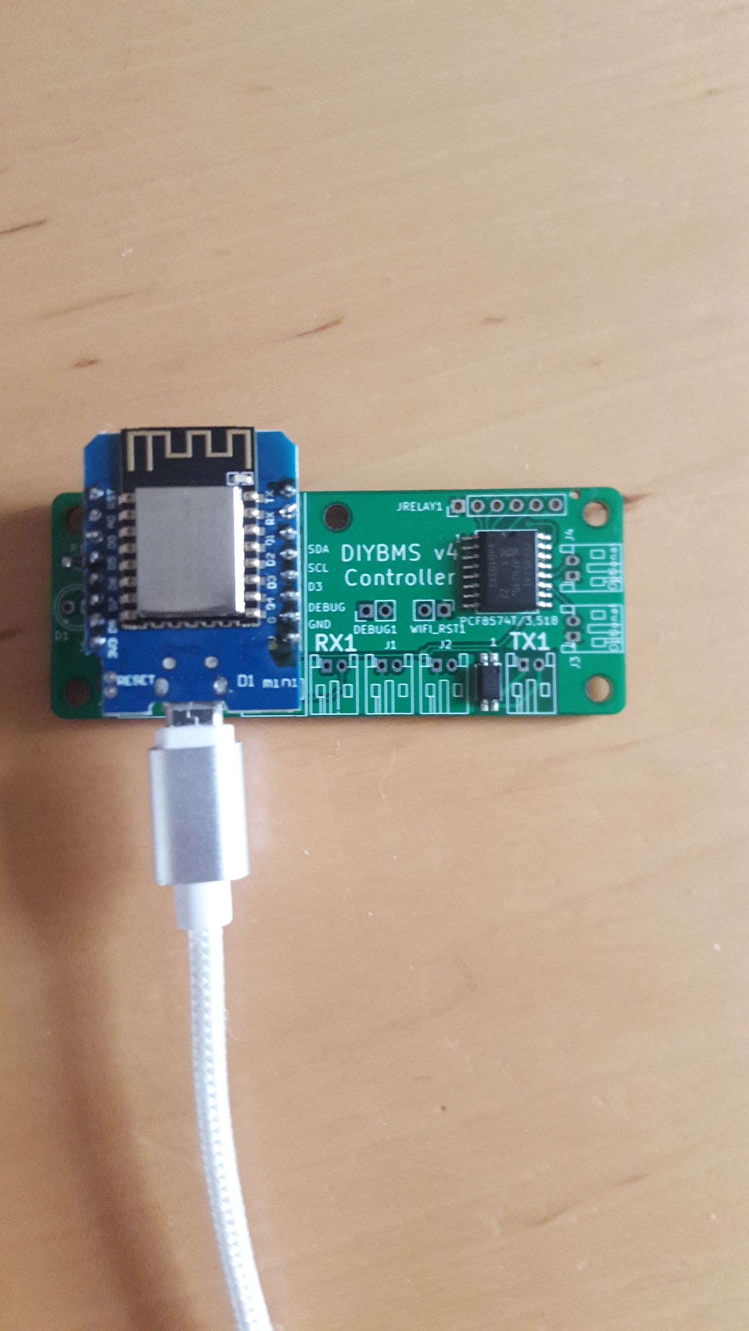
You have the ESP and controller board upside down - hopefully just for the photo 
2 Likes
Was quickndirty for the pic, now correct direction.
1 Like
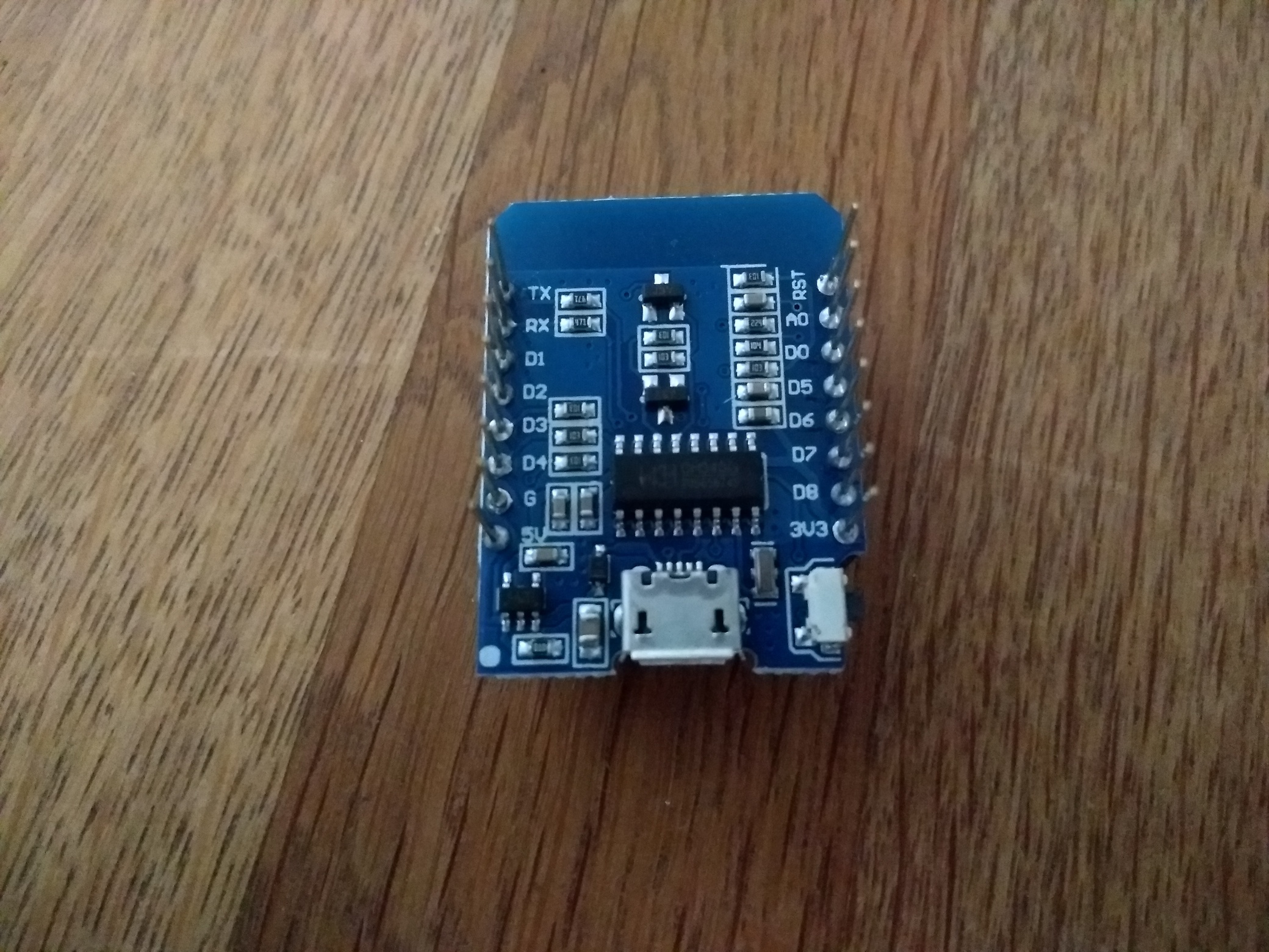
That is not a genuine Lolin D1 Mini.
It does the job though. Thanks all, I’ve managed to do the reset by grounding pin D3 during a boot. All sorted.
@stuart or anyone else, is there are way to blank the ATTINY841 I have one that I think I flash and and it seems to build all the versions 1 after the other, finishing off with v430,
I was following Stuarts YT guide, now when I try flash it with V421 I am getting an error
avrdude: error: program enable: target doesn’t answer. 1
avrdude: initialization failed, rc=-1
Double check connections and try again, or use -F to override
this check.avrdude done. Thank you.
*** [upload] Error 1
I removed the chip and soldered a new chip and flashed it, and it works fine so its not the module,
If you programmed it using the v430, the fuses will now be incorrectly set. That board (which isn’t available) uses an external crystal. For the sake of a single ATTINY - easiest to chuck it away.
Cool got ya !
I am just wondering why no reverse polarity protection on these boards ?
is this because a diode would stop them functioning ?
in regard to the printing on PCB
"DO NOT SHORT CIRCUIT , DO NOT REVERSE POLARITY "
850mA Dump load
also what would be the maximum charging in AMP be for this BMS system ?
is their a way to set a notification when your shunt and new controller are available for production ?
missed the ATtiny841-SSU by 2 days …
also I need 12000 resistors now as well … I aint soldering those … really wish we could que boards up to be fully assembled when all parts are in reserved stock …
also where is the complete part list ? what headers do I use JST WPJ ?
6 pin ISP header
https://www.digikey.com.au/product-detail/en/harwin-inc/M20-9980346/952-2121-ND/3728085
5 pin header
digikey.com.au/product-detail/en/w%C3%BCrth-elektronik/61300511121/732-5318-ND/4846831
better options ?
How many boards do you need for 12,000 resistors!?! What are you making?
They will be pushed up into GitHub, so you can set up a watch on that to see modifications
There isn’t one. The BMS does not directly control the charge or discharge but it can drive relays to protect the cells.
sorry 1 zero too many 1,200 6.2 ohms but swapped them for 6.8 ohms
also the marking on the back of the board said 850mah but
~4v 6.2-6.8 ohms is ~600mah ?
assuming this was from when the 5w was used ?
I know it is only balancing cells but their must be some form of math to determine when it will reach its limits especially when my 48v charger is pumping over 240 amps ~300amp peak
anyhow project seemed worthwhile to make not being locked into 6s ,7s, 13s,14s etc configurations will save me a lot of stuffing around when mix / matching packs
is their anything we could do to add a heat-sink to these ? ~5 watts of heat ?
1 Like
SURFACE MOUNT 6.2OHMS ±1% 1/4W 1206 ROHS, 4 in series with 5 in parallel gives 4.96 Ohm Equivalent Resistance.
Resulting in 0.84Amps at 4.2V and 3.55W power. 20 resistors provide 5W of power dissipation.
I am building a 22S lithium Titanate battery bank and looking at changing the resistor bank to a different value to suit the 2.8v cell voltage, as you just stated that there is a bank on 20 resistors (4.96 ohms) @ 6.2 ohms giving you 3.55W of power at 4.2 v battery voltage.
Calculation on a 2.8V cells @ 4.96 ohms only gives me a 1.58W of power dissipation. how much can i change this value of resistor to suit the lithium titante cells to get the most safe dissipation out of the bms boards, I have not yet ordered them from JLCPCB, I know i will have to change the BOM list.

Just doing some calcs of resistor bank to suit 2.8v lithium titanate cells, based on 4 in series and 5 in parallel
2.4 ohm bank gives me 4.08 watts (1.92 ohms of resistance)
2.7 ohm bank gives me 3.63 watts ( 2.16 ohms of resistance)
I hope my calcs are correct?, just wondering if this is the go with making this boards work the best with the lithium titanate cells?
Looking at the JLCPCB parts list they have a C247503, 2.55 ohm resistor 1%, 1/4w, in a 1206 surface mount with a stock of 4781 of them