If it is done with cable, then probably a controller pcb could be made even a bit smaller. So should be a good idea.

Perfect thank you,
Best regards Andreas
I want some sort of display (OLED is what I had planned) so I can rotate through status information without needing to pull up a browser interface.
I don’t see it as a security issue so much as just another light weight interface to see status at a glance.
I’d also consider this to be an optional module and be separate from the controller by a foot or so (there are limits to the I2C cable length).
Couldn’t a dedicated MQTT client with a display handle this easier?
To each their own, but my controller is located next to my modules in the battery box/compartment. A screen on the device would be a bit silly for me. Even the real estate for it would be a bit out of place to me, but I could see how some would use it. A buddy of mine likely would.
If it is there, I’d likely include it, because why not. However it would serve no practical use for me.
The controller should be reasonably close to the battery cells monitors, which should be reasonably close to each cell. I see no benefit to having a display there. I have to get into the battery box to see the batteries, and thus the display if it is on the controller board. If a display is going to be added it would be best away from those components. While I2C may not work, MQTT seems like a perfect fit here.
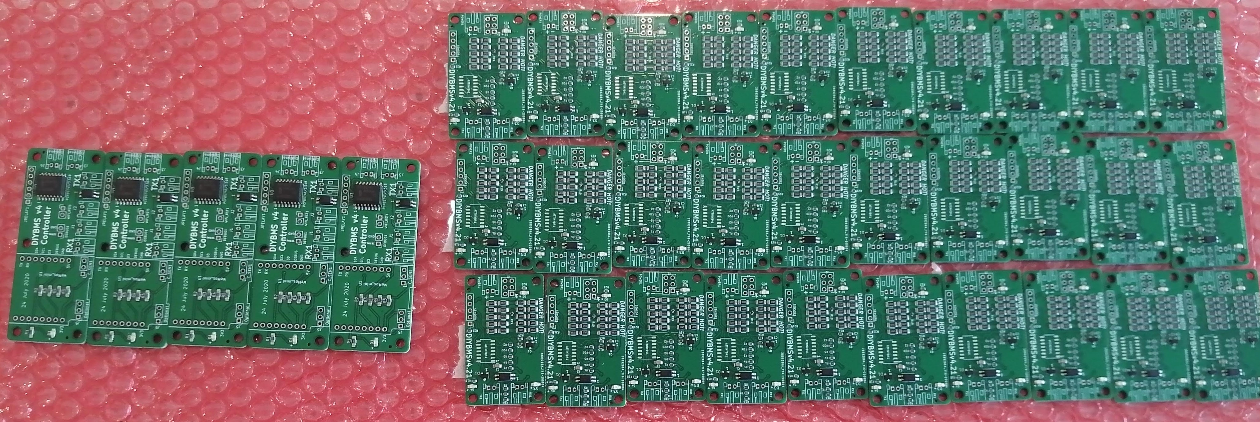
Looky Looky,
Just received the JLCPCB, Now just waiting on the ATTING841s which should arrive Monday/Tuesday
@stuart Can I make a request that the code for the current controller and new controller expands the number of banks, I am currently running 4 7s banks and am starting to collect and expand to 6 then ultimately 9 banks
Possibly, but it would require another networked device to receive and display the MQTT published data. This isn’t entirely a bad thing as the controller does not currently provide a time based graph (think grafana style dashboards). I know @stuart was working on this but I don’t know the current state of it.
Yes, I’m thinking that just a pin header on the PCB which can be configured for I2C, UART, etc… Something along the lines of how the EPEver charge controller has an RS485 port on it for a remote monitor device.
PCF8574 is NOT fitted, relay control not possible!
@stuart I have followed your YT video on programing the wemos mini d1.
I am getting this error “PCF8574 is NOT fitted, relay control not possible!” in the settings tab, the controllers were built about 2 weeks ago using the jlcpcb branch in git and the controller is PCF8574T.
I have to add I don’t have any modules connected or the relay board. Is this normal ?
https://jlcpcb.com/parts/componentSearch?searchTxt=C7605
EDIT: I have tested 2 controllers
You probably need to change the i2c address, you have a slightly different variations of the off chip.
Take a look in main.cpp file of the controller there is a comment in there about it.
Awesome so yes the file main.cpp is set to 0x38 I changed it back to 0x20 and re-flashed and now its working, thanks again Stuart
//PCF8574P has an i2c address of 0x38 instead of the normal 0x20
PCF857x pcf8574(0x20, &Wire);
Is there any other way to power the controller ? I have a DC-DC 4-38V to 1.25-36V 24V 12V 9V 5V Step Down Adjustable Power Supply Module, and would rather wire that up to the battery bank so that even if the inverter goes down I can still monitor the battery bank’s health,
Which pins would I use, GND and 5v or 3.3v ?
I use these ones: Lm2596hv 3a USB DC-DC Konverter 7-56v in 5v Out ideal für USB auf E-Bike Escooter | eBay
Thanks, but that takes it back to a USB cable and I what to move away from a USB cable
I stay at USB cable because of quick remove/replace controller in my installations. [Edit] For first tests I use a 48-5V from Ali with cables soldered to “5V” and “GND”.[/EDIT]
Added another row of 20 batteries to my 14s 80p for 14s 100p. While building the batteries and swapping one out at a time (spare battery) I discovered the modules have the balance setting (4.1v in my case) stored, so when you connect the module with a stand alone battery which is over, starts balancing immediately. Pretty cool!
@stuart, just ordered the 3.2" Nextion NX4024T032 to experiment with on my tracker. The new controller design looks great, I know you will sort it.
@stuart quick question … JLCPCB in a surprise move currently have the attiny in stock, but are currently down to only 25 stock remaining on the most commonly used resistor part (6.2Ω 1206 resistor). Do you know if I’m likely to get away with swapping for 1210 or 0805 alternatives and trust to JLC to resize the pads, or I should stop being so impatient and wait for the stock to come back in?
(so far I trust my soldering enough for the thru hole components, and the attiny soldering is ‘so-so’, but good enough, but all those resistors - shudder)
thanks
Tim
p.s. By writing this I’m also letting everyone else know JLCPCB have attiny in, so they’ll probably all be gone before I order anyway!
I’ve ran into this problem as well. You can go up to 6.8Ω (1206) - part number C25345 which will give a very slightly lower balance current, at the time of writing they have 21,000 of those in stock.
Don’t hand solder those, its going to be a pain and they are tiny!
Yes, thats a benefit of having a distributed system, even if the comms fails or used in isolation, the modules are autonomous.
ace thanks - order placed for 10 boards, and ~30 attiny remaining in stock, if anyone wants to get in there quick 