On v4.2 boards (not 4.21) the thermistor is in the wrong place. The readings you get are fine and accurate but you should limit the temperature to 50 degrees or lower to compensate.
If you swap the thermistor over then you can use the other code and higher temperatures.
I am mucking with the software to add features for current measurement and other things. I am discovering that when the wifi connects, the controller resets. I am failing to find how this happens.
I have rigged it so that the controller will be able to shut off loads. One of those loads is the wifi router. When I update the software, the device boots, and that shuts off the relay that controls the power to the wifi router. This kills my wifi router which takes a ridiculous 3 minutes to boot and become available. As soon as it becomes available, the controller reboots.
I have not bothered to figure out how to connect serial to get the debug serial output. For this situation, I have determined it is rebooting because I made the 3 second delay blink the LED in an obvious way.
Does anyone have suggestions for what is causing the esp to reboot?
EDIT: This is not repeatable. Sometimes it reboots, sometimes not.
I am new to android/ESP programming. How is space allocated in the EEPROM?
I have added a library (INA) that reads/writes to the EEPROM. The controller software from stuart also reads/writes to it. I have not paid attention to where these different modules are writing their stuff to the EEPROM, but I suspect I am suffering collisions.
Is the EEPROM thing so simple that I have to make sure that all users of the EEPROM class have a starting address that does not write over others?
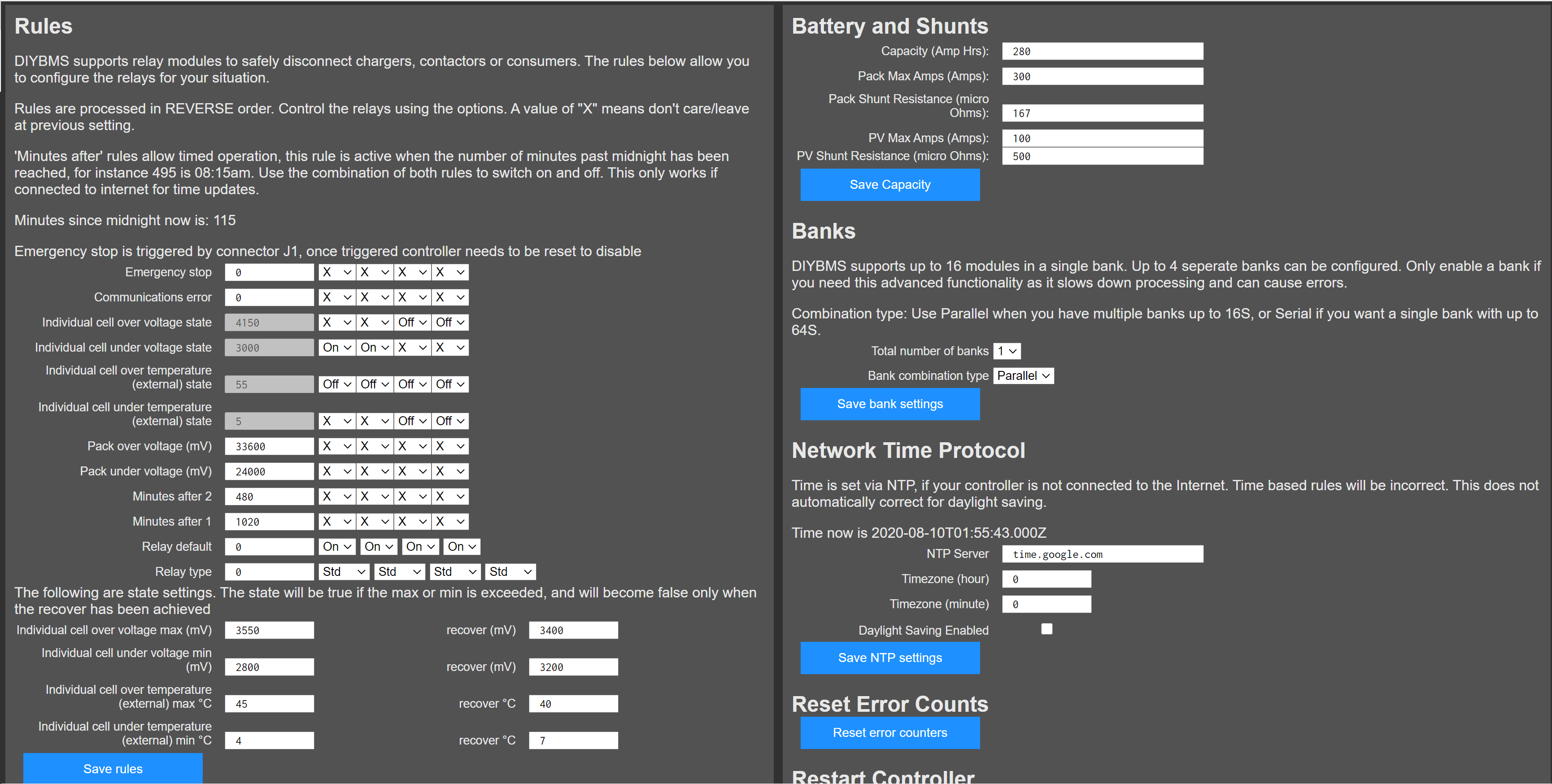
I am working on making the over volt, under volt, over temp, under temp have a recovery value. I am going to make 4 new states that are set via additional settings. For example, overvolt will be set when any one cell exceeds X, and cleared when all cells are below Y. Then I will replace the 4 similar rules with rules that respond to those 4 states.
I am not sure this works properly, but maybe it does.
These rules are a bit mind bending because if I set the rule to “off”, that does not mean that it will drive it on when that rule is not triggered. This should work because for example the under temp rule will drive it off, but the over volt negative will not subsequently drive it on.
Yea, I thought I reviewed that code and could not find where it reset. There’s only 2 occurrences of ESP.restart() and I don’t see how they could be hit.
I have been testing while power is coming from my laptop. When not updating the software I will be using a buck converter. I have no idea if this could be power related. It’s just a thought that maybe the lappy is on the edge? I don’t know…
I experienced random reboots on my 16MB Wemos D1 mini clone. After googling “ramdom reboots Wemos D1 mini” I saw forum posts about the 5v to 3.3v regulator on clones being undersized. When I check the markings on my regulator chip sure enough it was only rated for 150ma versus 500ma for the genuine Wemos D1 mini. When transmitting wifi the wemos easily gets to 150ma per the spec sheet. I was feeding 5v via the relay header. When I switched to feeding 3.3v into the 3-pin optional header the problem went away. If you are feeding 5v into a Wemos clone via micro usb or relay header and experiencing reboots check the voltage regulator chipp on your mini.
I updated the latest release with my changes. I have not committed anything to git.
I need to update the logic to deal with pack voltage using a recover value. Plus I can use the real pack voltage, instead of the summation.
Once I do that, the setting value on the left of the rules will be useless for all but the time ones. I have not thought about, nor have the need for, the time rules, but maybe they have a similar problem.
I will be ordering yet another iteration of my controller that will be updated with better connectors and 6 relays instead of the current 4.
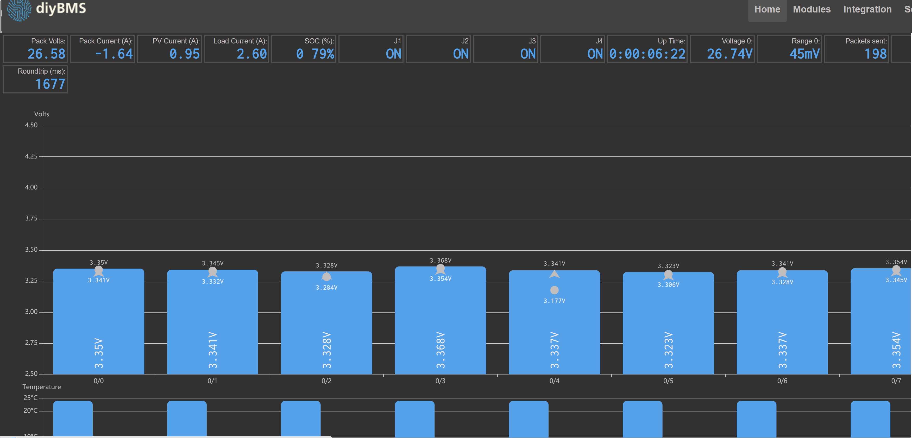
This is looking really good, DIYBMS is turning into a truly professional level bms with the help of the community. YES!! Current readings and pack SOC plus PV current!
and got stuck at “git: clone” not being available.
I did some googling and installed “GIT” (git-scm.com) and Github Desktop.
Not sure what did the trick of the 2, but after installing and restarting VB code program, it was a available command!
Second bump was "avrdude: error: could not find USB device with vid=0x16c0 pid=0x5dc vendor=‘www.fischl.de’ product=‘USBasp’ "
Using “Zadig” (zadig.akeo.ie) to get the correct driver for the USBASPv2.0 fixed this problem also
Now I see during programming all the nice flashes and it finished without errors.
I soldered 18 boards, 13 went perfectly.
I need to look under the microscope to see what is wrong with the other 5.
Probably just end up making 5 more (easier then finding and fixing)
Hi John, create a clone of the master branch into your own GITHUB repository and check in there.
Can you check in/commit each “feature” as you build/fix it? It then allows your changes to be merged into the core on a feature by feature basis and then retains your repository for your specialised controller version.
@John_Taves, when contributing code, the easiest way I have found is to first fork the original repository (upstream in git speak), then in your fork (origin in git speak), create a new branch and do your edits in that (local in git speak). You can then commit edits to local, push them to your origin and then create a PR to the upstream.
You can create the new branch, then simply copy your updated files into the folder for git to do its stuff.
My advice is, if the features are independent, do them in separate branches from your fork, and do a separate PR for each feature. If you have an open PR from a particular branch, git simply adds the further commits to the PR.
The key thing is to separate features into isolated units so they can be merged independently of each other - that way changes that are specific to your implementation can be easily excluded.
My changes are:
uptime counter
rules with recover values
relay status indicators
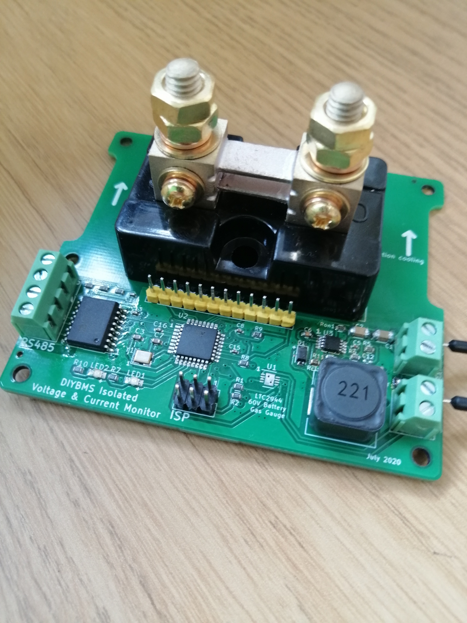
shunt measurement stuff
Only the shunt measurement stuff includes something specific, which is the fact that I use 2 INA226 chips for pack voltage and amps. However, if the code does not find the INA chips, everything should hide so that it works like normal. Also, if it finds just one chip, it does not display the PV info.
I would rather commit it all because other solutions for amp and pack voltage measurements can use the same code for displaying and settings. If one has a better solution for displaying, then I would want those improvements too.
The next person to put in a shunt measurement thing will be able to modify the code so that any number of different sources for the shunt info can be supported.
I am not asking how to use svn or git, so much as I am asking how changes are approved and put into the main branch.