Living in South Africa can be a right pain trying to get things shipped. JLCPCB/LCSC don’t have ATTINY841-SSU, so I found another company called chipmall and ordered from them, had my stuff Fedex and items are due to arrive a week later. if anyone else don’t not have the luxury for ordering from Farnell you could give chip mall a try www.chipmall.com
I’ve seen that as an answer to crossword clues, but its use in the US (AFAIK) is not too common.
Pins and needles? I can remember hearing that one as a young lad of 5. Quite common OTSOTP.
So i build this BMS for my small powerwall project but stumbled on some problems.
i had some troubles to upload the code onto the cell modules but thats fixed now.
then i was exited to see if it works. so i connected tx to rx and back. connected a cell and powered the wemos. so i am looking to the gui on the webbrowes but nothing does appear. am i missing something? tried to connect and disconnect serveal times but can not find the problem. i measured the tx and rx with the oscilloscope and saw the wemos sends data from tx to rx cellmodule but there is nothing coming out of the rx of the cell module. the cell module itself seems to work. red light comes on sometimes and i feel heat on the resistors when the led is on.
is there a debug guide for this?
pleas let me know what i can do to fix this.
yeah, i just checked the schematic and i made a mistake while measuring. i put my probe on one wire of the tx and the gnd of the probe on the other wire of the tx and i dit the same for the rx side. so i saw in the schematic that tis gives a short through my oscilloscope haha.
so when i disconnected one of the 2 ground i had signal on rx and tx but still notting to see in the web browser. any idea on how to go further?
first: the green leds blinks once or so when i connect it to power. but it does not light up when connected to the controller. somethimes the blue led blinks.
second: no the ignored packet does not count up.
third. i did not program the module with platform io. i tried this but it failed every time. i used a atmel-ice to program my module. what i did instead was. when i pressed upload in program io it gave an failed warning but i saw it generated a hex file. so i took that file and and uploaded it to the attiny through atmel studio. so i am not sure if i set the fuses. my best guess is that it just like pressing upload in platform io.
Okay, best guess the fuses are wrong. The module is running at a slow CPU frequency.
There are 3 fuses bytes that need programming, the vales are in platformio.ini file and you will have to work out how to do that with the programmer you have.
oke i will look in to that tomorrow. can you tell me how to set the fuses or where to find that?
i mean by that what are the setting for the cpu like clock speed scalers etc? if you dont know the setting by heart what i guess you dont :p, pleas tell where i can find this.
i can fix this manuel in atmel studio then i dont have to do an new upload.
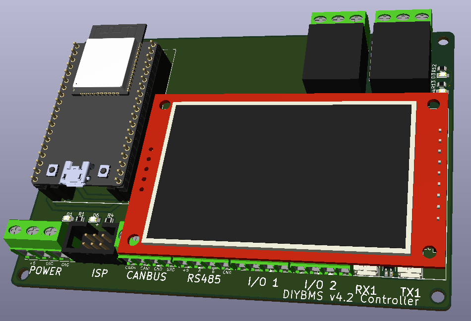
Just for information, this is the new controller design I’ve been looking at. It fixes a number of issues people have had and also improvements requested.
Please don’t ask about availability - its going to take a long time to get this working reliably and doesn’t “physically” exist yet. It may not work!
It has…
ESP32 - both DevKitC and Pico supported
Interface for CANBUS
Interface for RS485
A large colour touch screen (optional)
Eight I/O lines
Two ports for modules - allowing up to 128 modules on 1 controller
Two mechanical relays + it will likely have two or more solid state relays
DIN rail mounted case
ISP programming port for automatically programming the modules/shunt etc (no need for platformio or usbasp adapter)
All of the above is interfaced to the ESP32 using SPI interface and every available I/O pin is used!