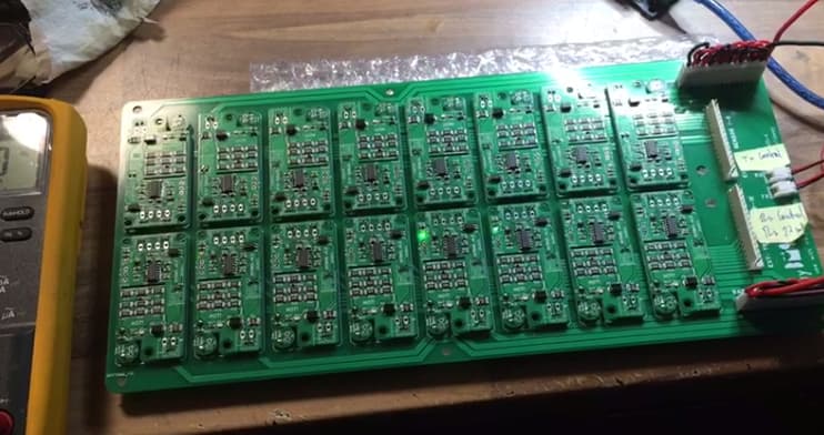
@stuart
how is the progres with the 16s all in one board?
i need to upgrade the battery soon and have to order 4.5 modules, but the single board would be much more practical for me.
Hello @stuart , Today I checked everything once more and there are no errors until the battery needs to be calibrated.
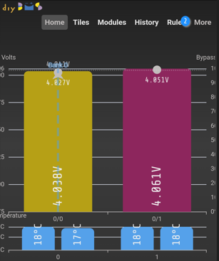
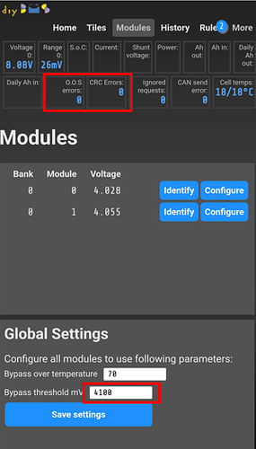
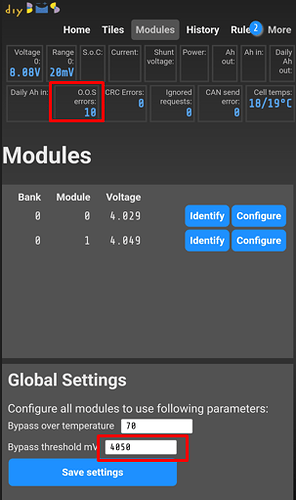
Now I set bypass threshold mV 4050 and immediately all modules start to flash D4 led synchronously.
When I tried using the small 5 cell pack, the calibration worked.
I don’t understand why it doesn’t work when I connect it to a large pack.
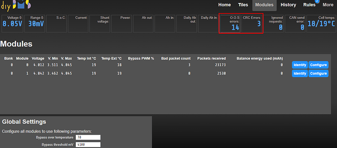
Yes after 12 hours of operation I got “OOS errors”
Where do I find the problem?
Hey has someone designed a v4.5 Board for prismatic Eve lf280k cells with new 2-screw terminal from nkon? (See Eve LF280K Prismatic 280Ah - LiFePO4 - 3.2V A-grade - Prismatisch - LiFePO4 - Wiederaufladbare Batterien | NKON)
I want top build a 16s battery for multiplus2
Keep an eye on YouTube hopefully get an update out this week, along with release of the code/PCB (prototype!)
i want to change the balance resitors to 6,8ohm for about 500ma balance current.
can the board handle the current specialy for other parts, heatsink is no problem i will cool that thing down.
but in case something goes wrong with the fan, does the balancing stops at high temp or will it burn to death?
question about the new balance algorithm, what will happen if i set start balance at 3,4v and deviation at 30mv
if 15 cells have 3,45V and one 3,42V the 15 cells start all to balance or just one by one?
Balance will stop if the temperature is exceeded - regardless of fan or heatsink.
Any cell going over the 3.4V (in your example) would start to balance - so potentially 7.5Amp of current flowing!
The deviation is only for the “run away” cell feature (or the active balance relay).
Hi,
Thanks for your sharing.
What is the wire length limit between your board and the batteries ?
What wire section did you use for this connections?
As there is passive balancing, this involve current in the wires so voltage drop in the measurements.
Do you know if the software will stop balancing before measuring the cell ?
My questions are for modules V4.5 but also interested to know how the wiring should be done for the “All In One” new monitor
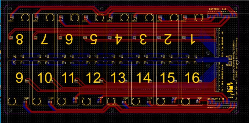
First of all, I created a more efficient design to use V4.5 (fatter tracks, without crossings and definitely more efficient.) I share it with pleasure.
The cable I used was 18AWG and the longest distance is approximately one meter.
It works efficiently in combination with an active capacitor balancer.
In the old design you couldn’t use the full speed, but with the new design, the modules operate at 10K without problems.
When I had the V4.4 modules, I did notice interference in the voltage reading when matching, passive and active balanced, but with V 4.5 this problem is no longer present.
As for the cables, there are 32 cables from the batteries to the v4.5 module board and other cables (17) (I didn’t want to share them) from the battery to the passive balancer.
As I run out of relays available on the controller, I activate and deactivate the passive balancers remotely with 2 relays via Wifi
I imagine, but I can’t be sure, that with the new Stuart cell voltage measurement system (all in one) the total number of battery cables to the system can be reduced to 17 Y cables (battery - and 16 positive) to connect with All in one and with Active Balancer.
I’m thinking of ordering some of these to test them, but I don’t know if they are still mature enough (prototype) and since my system works very well, I’m in no rush.
Finally , I have two boards for 6 V4.5 modules available in case you might be interested
For V4.4
For v4.5
And publish an ad in the sale section with an offer of 3 complete modules V4.4
Does the version that you have published already correct the two fixes that can be seen in the video in the design of the board? I mean the resistor and the blue wire.?
I think that just as Voltimetro Dan suggests, I will encourage myself to put a little higher resistances.
Although 6.8 ohm encapsulated 603 the largest are only 1/3W. Maybe we should be less ambitious with the resistors. opinions?
Thanks Rafael,
If i was starting today i will go direct for the all in one bms although still a new design, but as i just finished soldering and programming 32 modules V4.5 for 32 280Ah lifepo4 cells, so for now i will use what i have, but i was thinking if one day passive balancing is not enough to put wiring already outside so it will be easy to add a active balancer.
Passive balancing was not enough for you ?
they are complementary, the asset is permanently balanced and the asset begins to burn when the cells reach a certain level, close to the maximum charge, so having cells fairly balanced before this last moment I think is good and reduces the time in which the group of cells becomes completely equilibrated
for me now the balance power is not so important but the speed the modules talking to the controller is.
i use the dynamic charge function so if one cell spikes at near full charge the bms will lower the charge voltage over canbus and the inverter reduce charge power almost to nothing.
then 200ma are enugh to balance my cells in minutes but 500ma are better then 200 ![]() so i take that risk with the other resistors and i will use a big heatsink with fins and a 80mm fan to cool them down.
so i take that risk with the other resistors and i will use a big heatsink with fins and a 80mm fan to cool them down.
i also will use 1mm thermal pads for better contact to the resistors.
wanted to order the actual all in one board but chip shortage at jlc again…
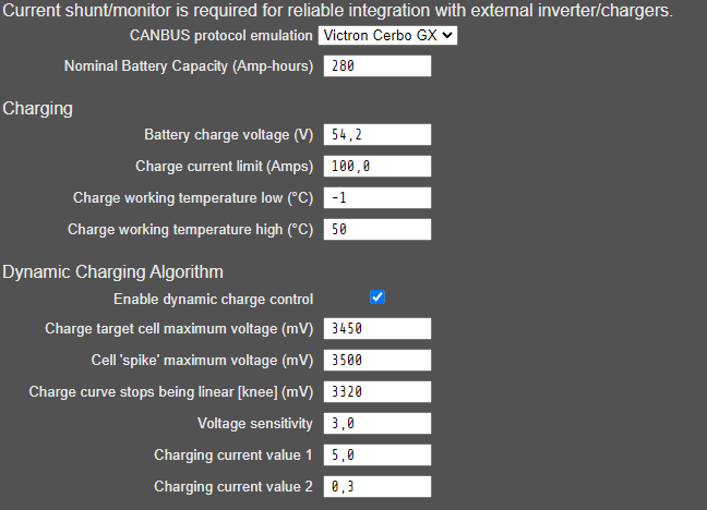
Hi, i want to use the modules V4.20 (orderd for my LiIon Powerwall 2020) with my new LFP 16s Pack. I also have a current meter an a controllerboard with display. I have connected the dyiBMS Controller with a Victron Cerbo GX. After connect the Cerbo to the inverters, the inverters go into error state “low battery”. My oppinion is, that the BMS decide to disallow charging and discharging. And also I can see, that diyBMS sends a temperature of 0°C to the Cerbo. At the modules are no external temperature sensors installed.
Do someone have an explaination?

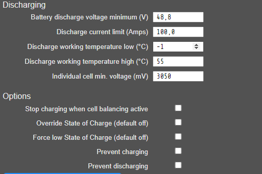
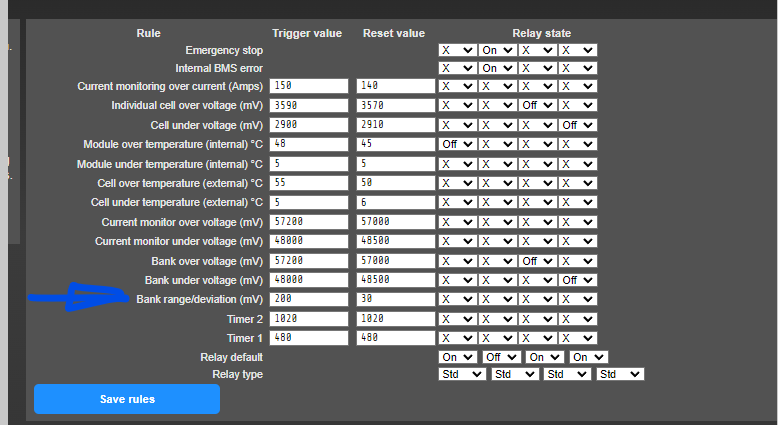
I have experienced a similar problem after updating the version of the controller until I realized that in rules, there is a new one: Bank Range/deviation (mV) that was too low, I don’t know if this could be your problem
I changed this values with same result. When I reload the diyBMS page, the charge and discharge prevention are the same.
Nick, you need to have the diybms current shunt board (or a newer controller) for the victron integration to be useful. That is the only way to get state of charge and current readings into diybms.
Hi stuart, I have a shunt board with 500A shunt/50mV and get voltage and current from the shunt over MODBUS. Do I need a temperature sensor for the victron integration? The 4.20 modules only has internal sensors for balancing.
Yes, at least 1 external temperature sensor is needed for cell monitoring.
Without any temperature sensor the diyBMS will send the Victron, that charging ans discharging ist disallowed?
