they are complementary, the asset is permanently balanced and the asset begins to burn when the cells reach a certain level, close to the maximum charge, so having cells fairly balanced before this last moment I think is good and reduces the time in which the group of cells becomes completely equilibrated
for me now the balance power is not so important but the speed the modules talking to the controller is.
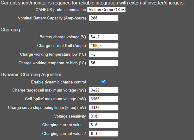
i use the dynamic charge function so if one cell spikes at near full charge the bms will lower the charge voltage over canbus and the inverter reduce charge power almost to nothing.
then 200ma are enugh to balance my cells in minutes but 500ma are better then 200 ![]() so i take that risk with the other resistors and i will use a big heatsink with fins and a 80mm fan to cool them down.
so i take that risk with the other resistors and i will use a big heatsink with fins and a 80mm fan to cool them down.
i also will use 1mm thermal pads for better contact to the resistors.
wanted to order the actual all in one board but chip shortage at jlc again…
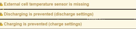
Hi, i want to use the modules V4.20 (orderd for my LiIon Powerwall 2020) with my new LFP 16s Pack. I also have a current meter an a controllerboard with display. I have connected the dyiBMS Controller with a Victron Cerbo GX. After connect the Cerbo to the inverters, the inverters go into error state “low battery”. My oppinion is, that the BMS decide to disallow charging and discharging. And also I can see, that diyBMS sends a temperature of 0°C to the Cerbo. At the modules are no external temperature sensors installed.
Do someone have an explaination?
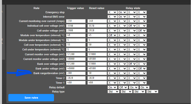
I have experienced a similar problem after updating the version of the controller until I realized that in rules, there is a new one: Bank Range/deviation (mV) that was too low, I don’t know if this could be your problem
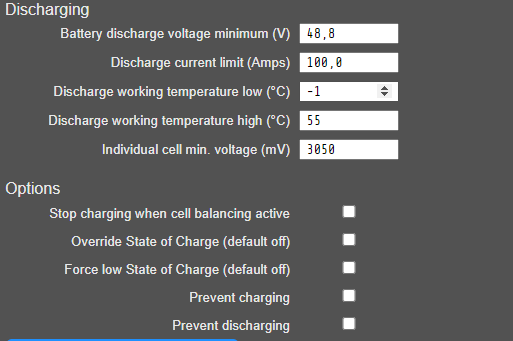
I changed this values with same result. When I reload the diyBMS page, the charge and discharge prevention are the same.
Nick, you need to have the diybms current shunt board (or a newer controller) for the victron integration to be useful. That is the only way to get state of charge and current readings into diybms.
Hi stuart, I have a shunt board with 500A shunt/50mV and get voltage and current from the shunt over MODBUS. Do I need a temperature sensor for the victron integration? The 4.20 modules only has internal sensors for balancing.
Yes, at least 1 external temperature sensor is needed for cell monitoring.
Without any temperature sensor the diyBMS will send the Victron, that charging ans discharging ist disallowed?
I am preparing a schematic for the Spanish group, but I have doubts about how RX and TX are connected between 2 All in One and the controller for a 32-cell system. Would someone know how to help me?
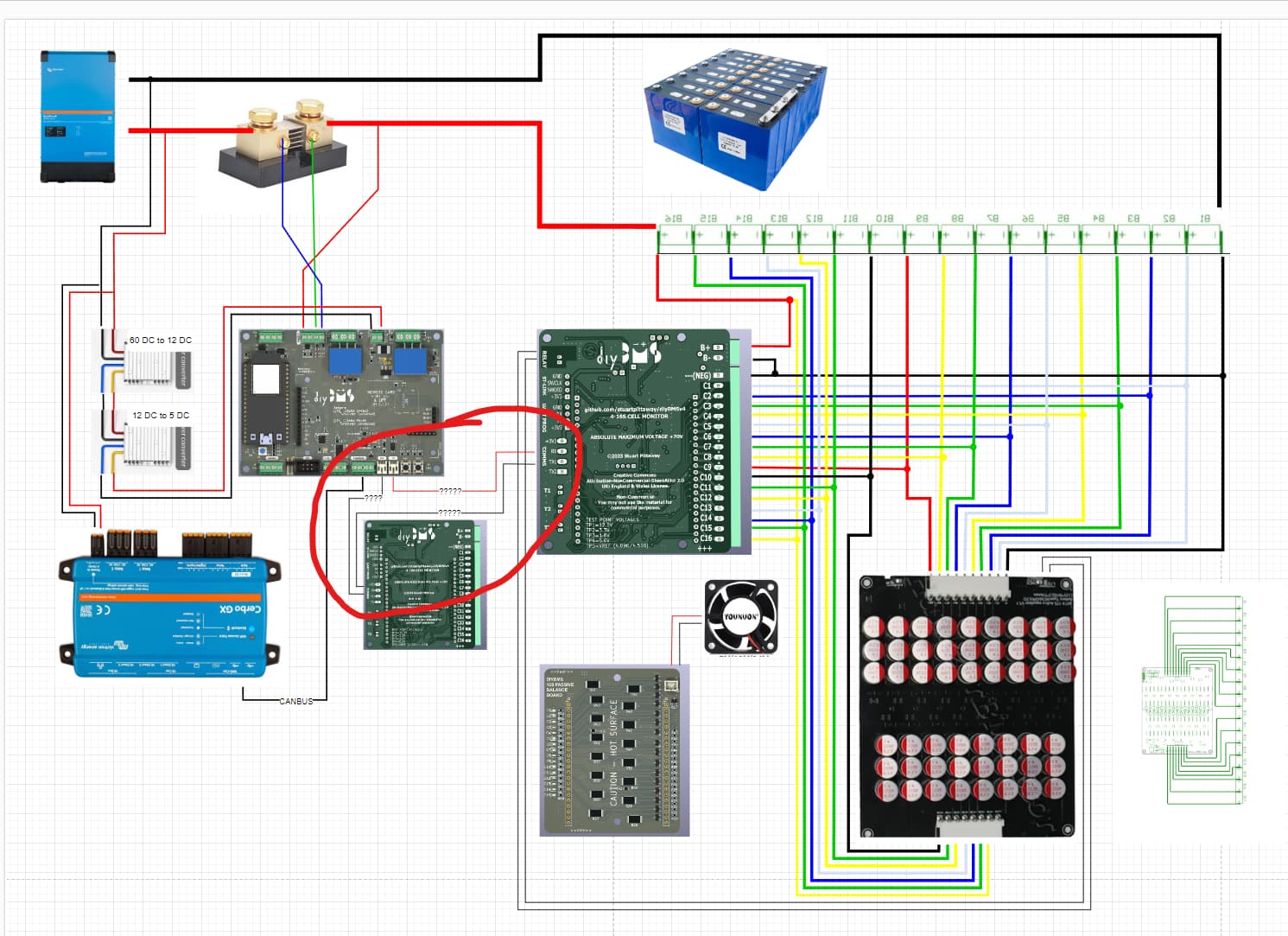
the tx1 and tx2 confuses me too
@stuart
the all in one module is labeled C1 to C16 but the software is still 0-15?
could you change the numbering in the firmware to 1-16?
this 0-15 was always confusing for me. if i see cell 7 have a problem it does not correspond to cell 7 in the pack…
can you make the pcb slightly bigger where the connectors are for temp program and comm.
and write there for what this connector is. when its mounted you cant see under the board.
also the pwr jumper cant be disconnected with the balance board fitted. or it is on purpose to disable balancing if program run?
@stuart , what are your thoughts on stacking two 16S passive balance boards on a common V490 AllinOne Monitor board, perhaps populating TH1 on one and TH2 on the other as a means of increasing balance current? Header pins are supposedly rated for 4-6A, but I don’t believe we need to get that carried away!
thought the same today but then the lower balance board cant be active cooled.
better you swap the resistors to 6.8ohm for 500mA balancing but you need a good cooler
Fan could be mounted on the edge of all boards, blowing air in between boards.
its not enough i think
I don’t think so either, I have ordered 6.8 and 8.2 ohm 2W resistors and the same package to do tests, but contact with a dissipation surface is essential, another thing is to mount a second group of L-shaped resistors in such a way that it can be placed on both the heatsink and the fan, but it will be a bit Frankenstein
well a additional balance board could be placed under the all in one module, then both sides can be cooled.
but this will be also a frankenstein ![]()
and its not so compact anymore.
tell us your experience with the 6.8 ohm resistors when its ready.
i will wait a month till i order, maybe stuart improves something.
i have found some suitable heatsinks from china:
That jumper will likely disappear in future versions, just useful during prototype stages.
Those look good. Don’t worry too much about the heatsink my solid aluminium bar and fan seems to work really well during balancing.