DIYBMS v4

since then I was not using this feature. When I figured out that it is not working, I have made an electrical workaround. But I can test it and let you know.

BTW:
The fix for communication (enqueue_task) works perfectly fine so far: 2 weeks uptime - no issues

is DVCC for victron working with this pzem-017 or even without a curent monitor?

Either the PZEM or the native DIYBMS current monitor will provide current and voltage readings into the Victron via CANBUS.

The DVCC should work from either

DVCC does work even without a current monitor. Now how accurate are the voltage level alone to instruct the Victron to do this and that, is obvs debatable.

What is the address on the i2c bus?

Thanks for the legwork on allowing communication with different 485 devices! I think the Junctek KG-F shunt is another great option, and have a working sketch that communicates with it via 485. I’ll work on a pull request.

image

Here’s a parsed data dump of what variables the KG-F shunt transmits via 485:

Command:0, Address:1, Checksum:215

Good Checksum!
Sensor:SHUNT, Vrated:100Vdc, Ampacity:400 Amps, Version:1.04, S/N:10

Command:51, Address:1, Checksum:67
OVP: 30.00Vdc, UVP: 0.00Vdc, POCP:0.00A, NOCP:0.00A, OPP:0.00W, OTP:30degC, Recovery Time:5s, Delay Time:0s, Capacity:20.00Ah
Voltage Calibration:0V?, Current Calibration:0A?, Temperature Calibration:0degC?, Reserved:0, Relay Type:0, Current Ratio:1
Voltage Curve Scale:50V/div, Current Curve Scale:1A/div

Command:50, Address:1, Checksum:186

Good Checksum!
Voltage: 11.79Vdc, Amperage: 0.00A, Remaining Capacity:16.03Ah, Cumulative Capacity: 0.05Ah, kWh: 0.00kWh, Runtime: 0d:1h:49m:36s
Amb. Temp: 20degC (68.00degF), Power: 0.00W, Output: ON!, Curr. Dir: REVERSE, Batt. Life: 173 Mins, Batt IR: 33.33mOhms
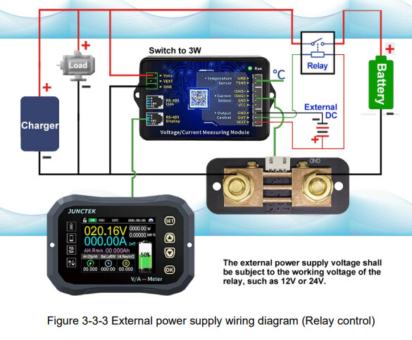
That looks interesting, is this from AliExpress or banggood?

[KG140F high precision coulomb counter lithium battery battery car battery indicator lithium iron phosphate capacity detector|Battery Testers| - AliExpress]
[Kg-f 120v 100a 400a 600a lcd power display battery coulometer coulomb meter battery indicator tester phone control Sale - Banggood.com-arrival notice-arrival notice]

Seems to output very similar values to diyBMS native current monitor - except for state of charge %.

Is the RS485 using the modbus protocol? If so it should be trivial to integrate.

1 Like

AliExpress. Link to manufacturers store.

Junctek also recently released the KL-F variant, which is essentially the KG-F minus the remote display. I have confirmed with Mr. Kang Lee the KL-F still supports 480 comms to 3rd party devices, and a display can also be added down the road. KL-F variant

$5 off coupon from a DIY Solar forum: 2S5SY35FREVV

Short vid of KL-F

Unfortunately comms is not Modbus, it’s simply ASCII strings. KG-F Series User Manual (2).pdf (4.3 MB)

Here’s the sketch used to parse the serial stream: Juntek.ino (7.0 KB)

Ok, doesn’t really fit very nicely with the existing logic/code inside the controller, but should still be possible to interface with it.

1 Like

Agreed, pretty straight forward. There’s a glitch in their CRC calculation, where one of the data streams (Command 51) doesn’t utilize all variables to calculate the Checksum (voltage and current curve scales do not contribute to the CRC). That’s the only bug I’ve found. The workaround is in line 86 of the sketch.

@stuart what is this branch for? New-Controler-After-20210310

I started looking at alternative parts due to the chip shortage, but was a futile activity because everytime I decided on a different part it went out of stock!

Stick with the master branch.

I am currently building a battery pack for a Quattro 48 10000 VA charger/inverter. This is going to run as a battery-diesel generator hybrid system so i expect to two full charge discharge cycles every day. Setting up with a 16S pack for now with 280AH EVE LF280K cells. Due to the big inverter and potential high peak current i will likely need to use external 500 A automotive contactors and will most likely also need a precharge.
Have tried to investigate this a bit, but as far as i can see there is no option to control a precharge relay with the current firmware ? Anyone tried to implement this themselves in the firmware ? Maybe it is easier to just do it with external hardware. REC has a module for this that is not super expensive.

Due to the nature of the system where i do a full discharge and charge often, it would be great if i could tell the Victron Quattro to disable charging/discharging when battery is full/empty instead of having the battery disconnect from the Quattro unit each time.
I guess the normal way of doing this is to set the charge/discharge voltages on a pack level in the Quattro unit, but it would be cool to be able to have warning cell high/low level in addition to the alarm cell high/low that now disconnect the battery. Then i guess that i can assign relay rules to these warning levels and tell the Quattro to stop charge/discharge with these relays. Do the firmware currently support this or anybody implemented this themselves ?
I guess some of this can be done with DVCC over canbus, but unfortunately my unit is to old to support DVCC. It only support a to turn off and on charging/discharging with some digital/analog inputs on the unit.

I guess one option would be to not have any relays or disconnects at all. Just use the Victron two wire BMS option on the Quattro and then use the relay output from the DIYBMS to control the Quattro to stop charging or discharging. Anyone using the Victron Multiplus or Quattro like this ? Seems like this is what the connection diagram for the 123SmartBMS looks like with a Victron charge/inverter.
The big advantage of this is that i do not need any precharge and my charge/discharge current is not limited by the current rating of some mosfet or relay. Potentially also have higher reliability as there is fewer components in the high current path of the battery.

Love the project and the work done some far, i will definitively join the pateron as a thanks if i end up building myself a unit and use it

@stuart
or anyone who can help

i just noticed that you can set how many parallel banks (cells) you have…

so right now i’m running 7 cell modules on a 7s4p battery consisting of large 1kw BMW modules. i just have them in parallel as well as the balance leads…

so if i want to set up the diybms as 7s4p i would put 7 cell modules on each 7s pack while still keeping the cells tied in parallel but instead of having the balance leads also in parallel just run them to the cell modules instead… correct?

Not quite…

The parallel setting in diybms allows you to have seperate “strings” of cells, although you have a “4p” setup, because you have put them in parallel (by wiring them together) they become a single cell as far as the BMS is concerned.

What you could do, is to split that larger pack in half so you end up with two smaller battery packs, 2x 7s2p. This would then allow you to put more diybms modules onto those split cells which then provides greater balance current (if you need it).

If the setup you currently have is working for you - leave as is!

Uggh. I was trying to troubleshoot my modules, and must have accidentally switched RX and TX cables on the controller board. It released the magic smoke. Seems to have fried the board, ESP32, screen, and SD card. It’s such an easy thing to do, it sucks the cost is so high.

Can I suggest a different cable connector for future revisions so nobody can make this costly mistake?

you made the mistake before changing the RX and TX cables. As a precaution, these cables should never be changed with the cells powered. If by mistake you have exchanged them, when feeding the cells they simply will not communicate and you will not have the magic smoke.
I also did it at the beginning (burn the ESP32 controller) and learned this lesson.

I’m surprised its taken all these out - you end up with a dead short, so its possible the ESP32 is still alive, but the 3.3v regulator on the ESP board (or more likely the diodes near it) have died.

I’ve recovered ESP8266 from similar damage previously. Not sure about the TFT screen, I’m surprised that was affected.

I have TX connectors red, on board and cable. Next level Is on my cell boards 4r7 resistors in series with input and optocoupler. If Is conection bad, smoking only 4r7 resistors…