during the build / upload i get several “errors”: #warning “Please include TimeLib.h, not Time.h. Future versions will remove Time.h” [-Wcpp]
and
‘SPIFFS’ is deprecated (declared at C:\Users\Frank.platformio\packages\framework-arduinoespressif8266\cores\esp8266/FS.h:269): SPIFFS has been deprecated. Please consider moving to LittleFS or other filesystems. [-Wdeprecated-declarations]
“Upload file system image” doesn’t work directly.
when i start it twice, or disconnect and reconnect the usb cable, it goes without problems
and again, with just only the wemos, i dont get any errors except communication time out
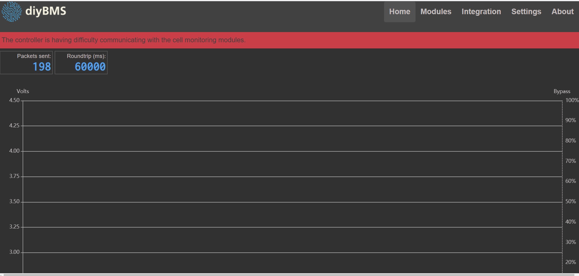
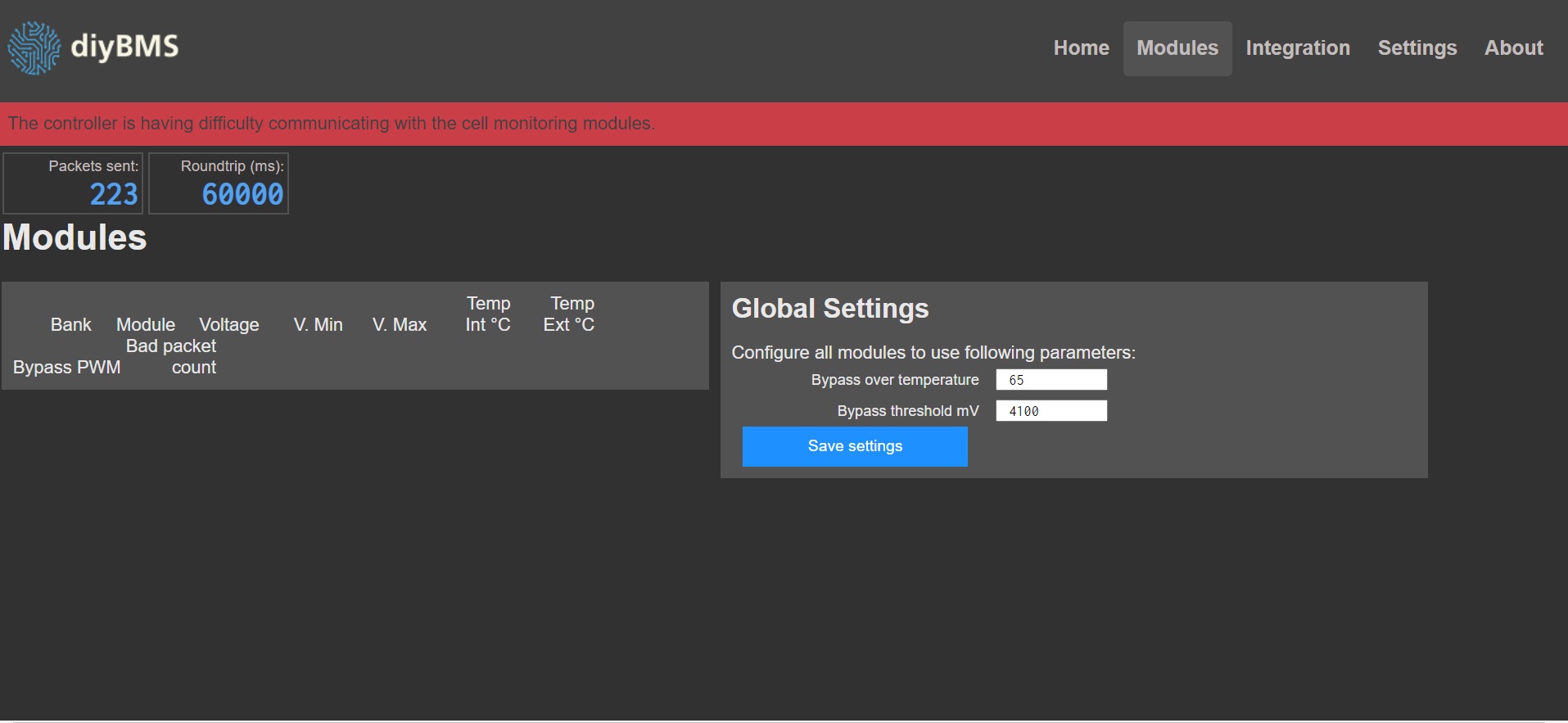
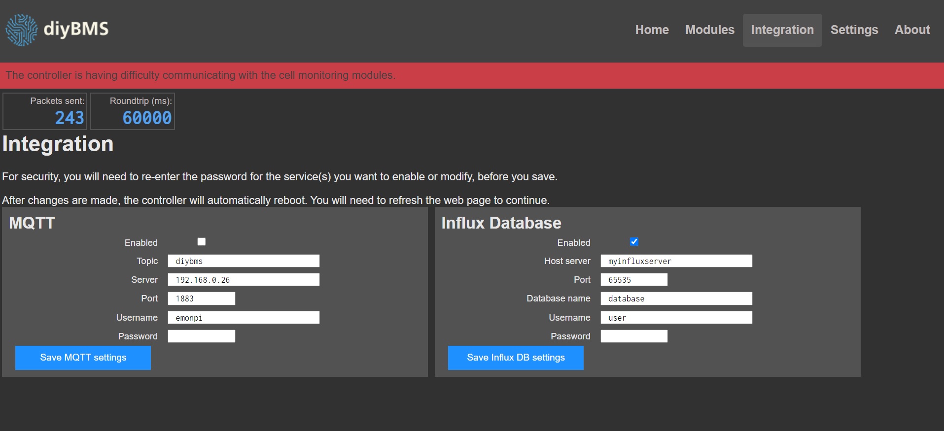
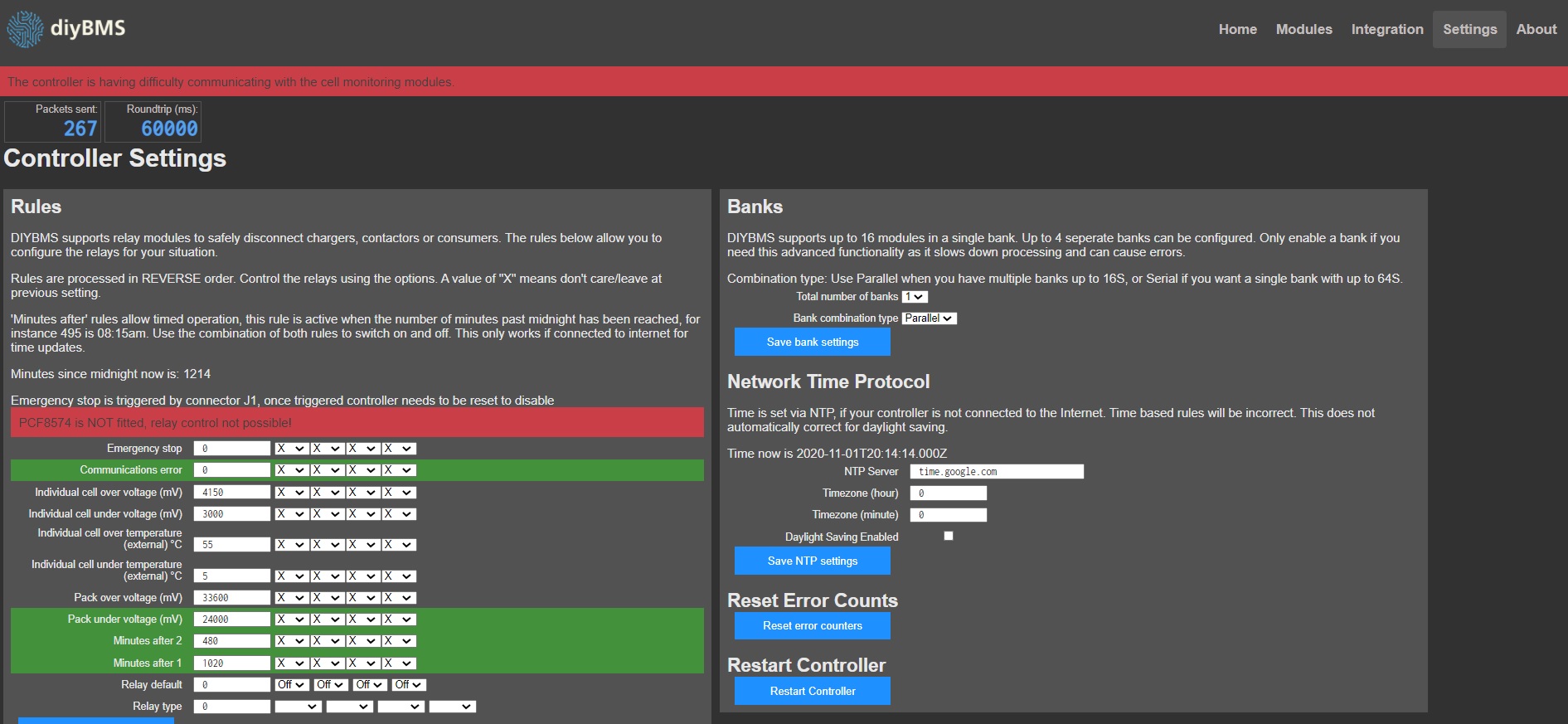
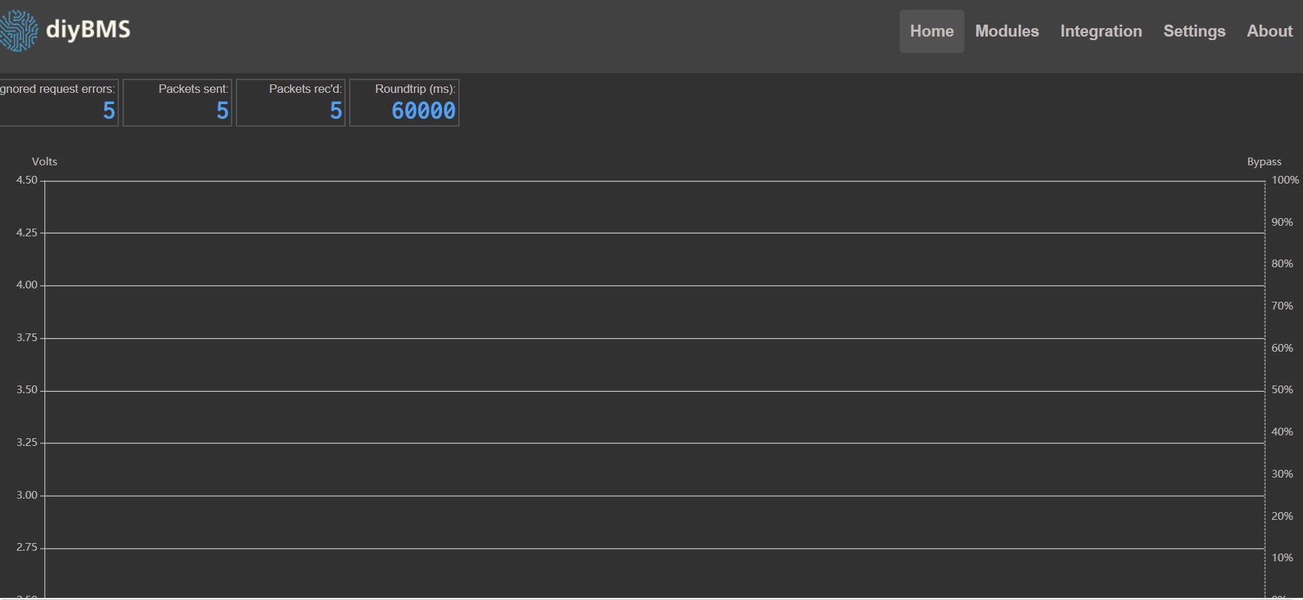
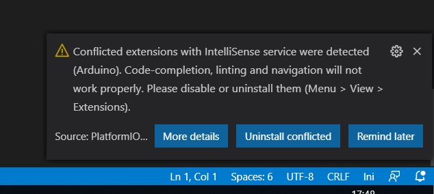
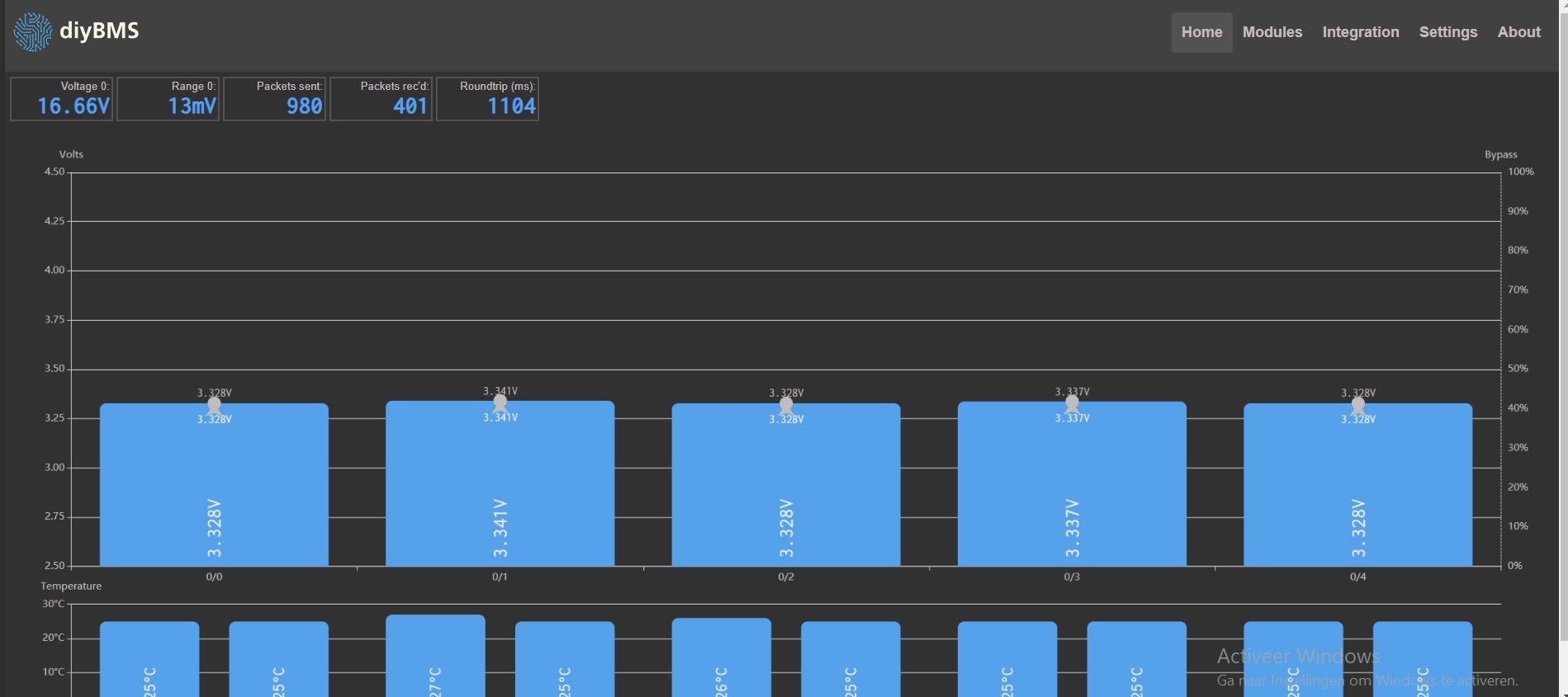
Is this the bunch of errors you talk about?
(see screen shots)
I have a spare laptop, and I’m going to make a fresh installation of visual and PlatformIO.
Internet is slow, that will take half a day.
I hope it’s corrupt installation of the software.
I’m running out of options here!
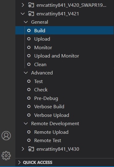
followed the steps on the videos, and don’t get any impressive errors.
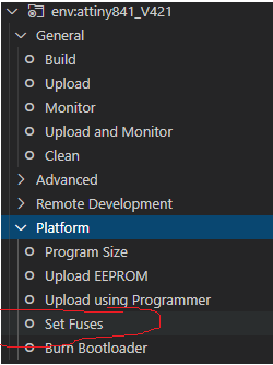
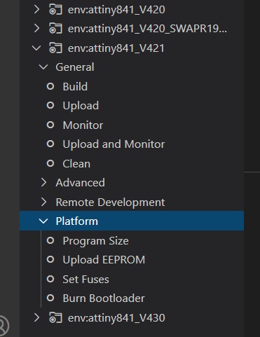
You shouldn’t need to do this step individually when programming the modules, however I have seen some instances where the fuses were not set correctly and that causes the modules to operate incorrectly - normally with comms issues. You run SET FUSES then use the “Upload using Programmer” option.
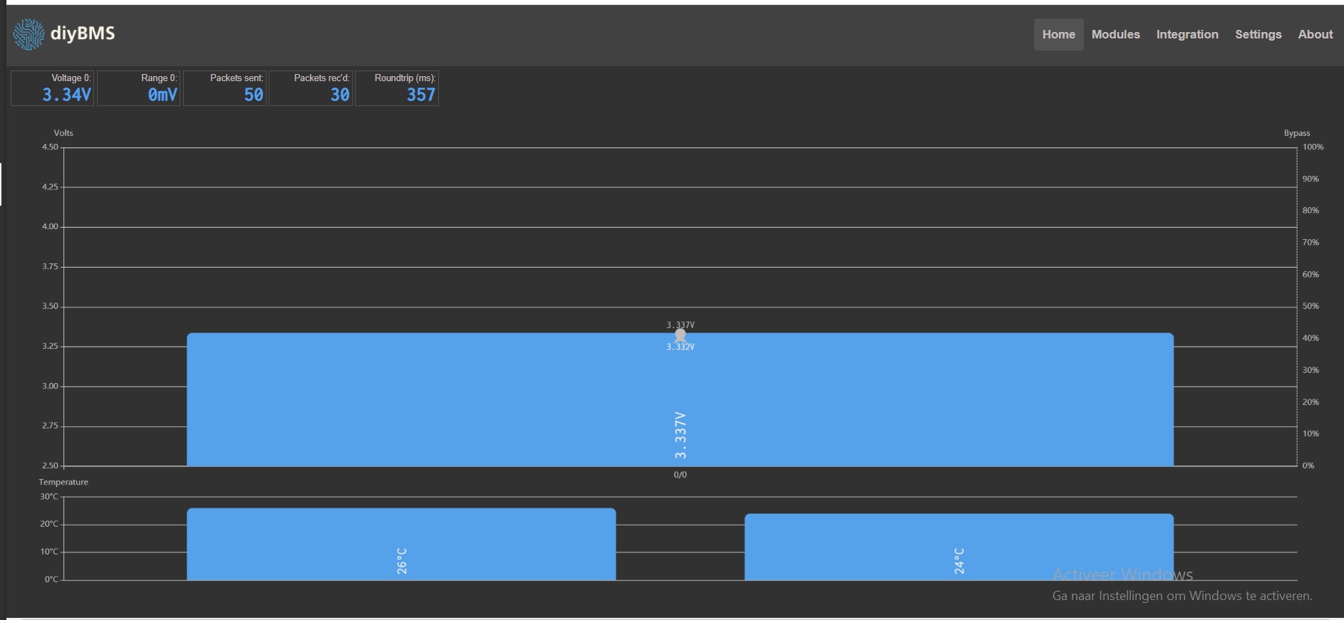
Thanks @stuart. So yes I measure close to the module with the voltmeter. I have one of those short leads (very thin gauge with the JST connector) where I then connect my lab supply with crocodile clips which cables are rather long I would say, around 50-60cm but the gauge is quite big so there shouldn’t be much voltage drop and I can confirm the voltage as I say since I measure 5cm close to the module and that voltage fluctuates very little 0.01 V where the reading on diyBMS is 0.09 V so its not much as you say it’s probably within range.
The cable for PWR are the small leads (very thin) mounted with JST plug, any recommendation on gauge for the PWR cables and also length wise ?
So the module will continue to be in bypass until the temperature is high then lower current and when temperature is lower again it will bypass again ? It will go thru this loop indefinitely until the voltage get’s within range. Is this correct understood ? The temperature it uses is that the bypass temperature or another temperature internally in the module ?
It would be nice to know about this to understand the workings about diyBMS so one know how to react and inspect when you use it.
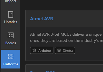
nope, and searching for atmel avr does not give me this as extention.
it does give “arduino” and after installing that extention it does show me.
sadly also provides me with an error:
I googled on the Atmel AVR and visual code…
it seems that you need to install studio7 (874mb) to be able to use “Atmel AVR” ???
I hope not needed…
With my internet speeds (3G) that will take a day or more to download…
soletimes if the atmosphere is good, we have OK speeds.
one of the down sides of living remtote.
I’m affraid that this does require me to flash all my + 50 cell modules again…
During initial flashing i didn’t get any errors.
Clean computer with no arduino history…
that apparently needs some more softrware installations then the video suggests…
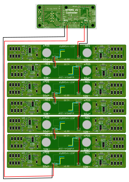
I need some help. I am very new to these topics. I have been able to mount diybms on leaf batteries, but I cannot communicate and the LEDs blink blue. Before checking all the wiring, I need to know if I have done it correctly, can someone confirm me?
The plates are assembled by JLCPCB and by the openenergymonitor store (controller), with which I discard bad welded.
Your post was blocked by the system because it appears you wrote it and then copied it into the forum. If you use the editor here and type directly into the page, it should be OK.
From the TX on the controller board connect this to the RX of a module - first connect it on a pin 1 to pin 1 and pin 2 to pin 2 basis. Don’t worry about connecting the TX from the module to the controller for now.
If that works, the LED should flash green every 4 or 5 seconds.
If it doesn’t, connect TX pin 1 to RX pin 2 and TX pin 2 to RX pin 1 (swap pins over).
If that works, the LED should flash green every 4 or 5 seconds.
@manuromero05 I think you have the same issue as above - just try swapping the pins of the connector TX on the controller and see if that kicks everything into life.
What is totally strange, as it seems to me exactly the same as before…
Except for the “creating ignored errors” by contacting Tx with RX directly.
(and now using a random board, all components, including attiny841 soldered by jlcpcb)
Hard to wrap my head arround it…
understanding why it sudenly works…