Not really, its just a point in time compile.
You can see from Github, its 3 changes behind the master code now.

@taumarc I’m about to do a large merge of code into master with a lot of changes so I’ll do a release at that point.
Not really, its just a point in time compile.
You can see from Github, its 3 changes behind the master code now.
@taumarc I’m about to do a large merge of code into master with a lot of changes so I’ll do a release at that point.
Hi Stuart
Great work you (and the others) are doing 
I thought my weekend was saved, the wife out the house and lots of time to test my new solder oven with your project…
Sadly I can now see that the LM4040BIM3-2.0 is not included on the BOM on github? I can see that you mention it in this thread… and it is also in the “picking list” in a subfolder… but not in the BOM…
So I would suggest to add it, saving someone else the trouble
I did manage to souce a local version called LM4040AIM3-2.0. (AIM instead og BIM), and as far as I can see there is no apparent difference?
I will give it a try anyway, even Farnell takes 4-5 days to deliver now…
BTW. Any change we can go down to 0603 in the next version? I will need glasses then 
/Heino
Hi, take a look at the jlcpcb branch on GitHub. That’s 0603 and optimised for preassembled boards. The lm4040 is no longer used
Well sadly I failed to find the branch of to JLCPCB, so I basicaly just downloaded the main branch as a zip-file, and used the fies in there… and here we are sadly missing the LM404 in the BOM list.
Sadly I have also had PCBs made from JLCPCB (and yes they should give you some kind of kickback) maybe PCBWay are interrested?
But since I am using the PCBs from the main branch, I am replacing the LM404BIM with a LM404AIM
I have also ordered a few of the newer 4.2 boards as I expect they draw a bit less power with 0603?
/Heino
The lm4040 still works, just make sure you order the 2.048V version. The A version is expensive but better accuracy.
@stuart Hello, I want to ask for some boards v4 pre-builded from JCLPCB, but they required BOM file which i found in the git project and the CPL file that i don’t found it. Could you please indicate me where i can get it ?
Thanks a lot,
Jonny
@stuart Thanks a lot for uploads the files. I try to submit those to JCLPCB but they come back to me showing that the coordinates does not match. It there any way from my side to do it ? Using some program or so ? I’m very new using PCB’s so need some guidance on it.
I was using files:
…\diyBMSv4\Circuit\v4_bom_jlc.csv
…\diyBMSv4\Circuit\v4_cpl_jlc.csv
Thanks a lot,
Jonny
Did you pick up the 4.2 branch? look here for the latest release
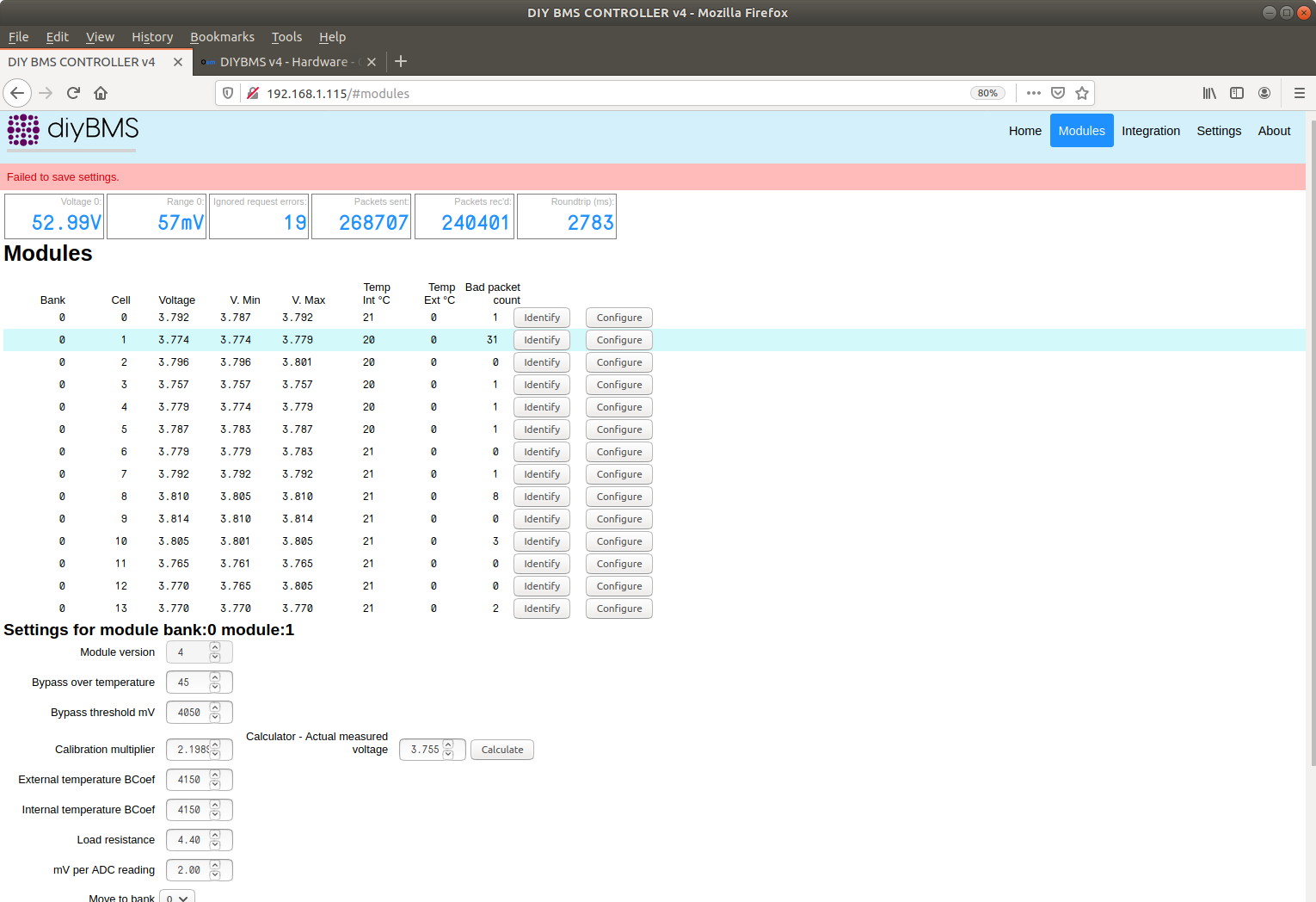
Anyone have experience of calibrating the modules. I’ve measured that actual voltages of my packs. I’m trying to set Calibration multiplier by using the Actual measured voltage Calculator box but when I try to save the setting, it always says Failed to save settings?
Refresh the browser window and it will work. It’s a cross site scripting security feature.
looks like you have the v4 pcb layout and the v4.21 bom you need to make sure you have the v4.21 file with the v4.21 bom
Hi,
I have built and set up an 18S pack.
I have the DIYBMS V4s built and communicating well when they are monitoring the cells. But when the charger kicks in, the communication fails and I get a pulse of 4 green lights instead of the normal 1 green light trail. It recovers when the charging voltage is removed.
Has anyone seen this?
Youtube video link:

Taumarc
Can you buy the in PCB’s already built?? (UK)
Not fully built but mostly. You still have to solder a few things but not too many.
Use the files from here…
What code did you use to program the modules and controller?
Got my second 14 built last night. Testing them out this morning one would not receive the message going round the chain. I touched up the legs of the ATTINY but it didn’t resolve the problem. I was about to give up when I noticed resistor R16 was missing.
Unfortunately I am 1 board short. I ordered a couple of spares just in case but 3 are dead so I only have 13 boards for a 14s. Anyone in the UK have a spare v4.21 board with ATTINY attached?
Hi Brian,
Got it ! Yep this ones are the right, was mixing the gerber files from older branch with the latest BOM/CPL, now is fine.
Thanks a lot.
I finally got an PCF8574, I soldered the chip in place but in the web interface I’m getting “PCF8574 is NOT fitted, relay control not possible!”. I even reflash the wemos and I’m getting the same error.
I need to do something in the firmware or in the interface to make it work?
No, did you get the exact chip as specified in the BOM or just something random from ebay/another supplier?
If not exactly the same, its probably got a different i2c address - look in the source code for the controller on what to change.
//PCF8574P has an i2c address of 0x38 instead of the normal 0x20
PCF857x pcf8574(0x38, &Wire);