I’m trying to figure out why you’ve posted this twice? My question was specifically relating to the availability of this component on JLCPCB for their SMT service.
That’s just down to the PWM - this tries to keep the temperature at the set point to avoid overheating. A flashing light is normal after a few minutes of balancing.
I’ve just ordered 50 modules based on the ‘jlcpcbassembly’ branch which uses the replacement TL432G-AE3-R in lieu of the AZ432ANTR-E1. I’ll report back once I’ve tested them. Has anyone else used this branch for new SMT orders with JLCPCB?
Whilst I haven’t built any of the modules yet, I’d like to thank @stuart for his immense efforts and time donated in putting this incredible project together.
If anyone’s interested, I’ll be hooking this into a new home build which incorporates the following:
- 21kW total of solar panels
- 17kW of solar panels feeding into a 15kW 3-phase Fronius Symo grid tied inverter
- 4kW of solar panels feeding into a Victron MPPT 100/70 charge controller
- 3x Victron MultiPlus II 5000kVA inverter/chargers configured for 3-phase providing hybrid/off-grid support
- 45x 280Ah LiFePO4 prismatic cells in a 15s3p configuration for 40kWh total battery capacity with the DIYBMSv4 (45 modules) providing cell monitoring and balancing. I’ll probably use an active balancer in parallel with the DIYBMS to help speed up and provide more efficient balancing to these large cells.
When the project is finished, I’ll be sure to provide some videos and information to everyone here when it’s done. We haven’t started building the house yet so this may be a while off yet.
Thanks again Stuart, I really appreciate your time and efforts spent on this.
1 Like
I’d also like to thank @stuart for creating this great project and all the others who have contributed.
I am testing v4.1 on a 14s80p battery made from recycled laptop 18650s. I’ll let you know how I get on. So far so good but old recycled 18650s have varied characteristics, and they may get more out of step than the modules can handle.
2 Likes
Stuart,
When pulishing over MQTT
after testing i see that not all data is coming trough.
i have 3 banks with 7 cells
I entered some test data because i am still waiting for my prints
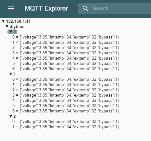
From the last bank only cel 0 and 1 are received.
If i comment out some data all data is received; so i think there is some limitation in tje json doc lenght.
Also tried to increase the StaticJsonDocument<100> and char jsonbuffer[100]; to 200 but no succes.
Trying to publish per bank and see what this result will be.
Thanks, if you can submit a pull request on the working code that would be great.
It may be simpler to change the “voltage” to “v” for instance to save some bytes.
Indeed,
Something like this already has a big difference;
doc[“v”] = 3.85;
doc[“Tin”] = 34;
doc[“Tex”] = 32;
doc[“bp”] = 1;
I’'l do a pull request after testing.
I think it might be the ESP8266 MQTT client that limits the size. e.g. Arduino Client for MQTT. Check the docs for the library used.
You could get rid of the keys completely and just send the data.
This would be a much better solution.
The documentation says thas these flags are in PubSubClient.h
I Can’t locate this header file, i think the API documantation is for an other class.
diybms uses AsyncMqttClient.
I’m looking for a similar approach for AsyncMqttClient
Yes I did say…
![]()
The other way would be to publish each bank as a separate message to a separate topic.
Brian,
Indeed the problem seems to be caused by tcp client not having enough buffer space:
Splitting by bank seems to be a good solution.
1 Like
That firmware has not been updated for a long time, platformio is the way to go!
It’s your latest code?
Hi,
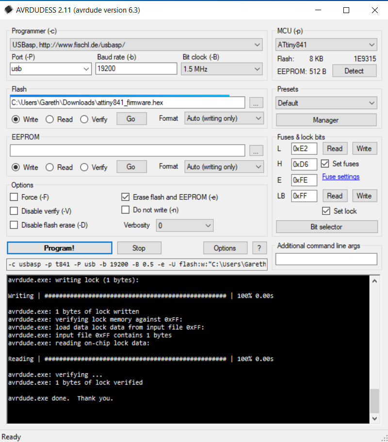
I also used the pre-built image from github and “AVRdudess”.
I have 18 boards programmed and working.
(Thank you Stuart)
I tried to build the image from platformio, but I was overwhelmed by errors that I could not remove.
@stuart, any chance of uploading an updated binary if there have been code improvements?
1 Like
Not really, its just a point in time compile.
You can see from Github, its 3 changes behind the master code now.

@taumarc I’m about to do a large merge of code into master with a lot of changes so I’ll do a release at that point.
2 Likes
Hi Stuart
Great work you (and the others) are doing 
I thought my weekend was saved, the wife out the house and lots of time to test my new solder oven with your project…
Sadly I can now see that the LM4040BIM3-2.0 is not included on the BOM on github? I can see that you mention it in this thread… and it is also in the “picking list” in a subfolder… but not in the BOM…
So I would suggest to add it, saving someone else the trouble
I did manage to souce a local version called LM4040AIM3-2.0. (AIM instead og BIM), and as far as I can see there is no apparent difference?
I will give it a try anyway, even Farnell takes 4-5 days to deliver now…
BTW. Any change we can go down to 0603 in the next version? I will need glasses then 
/Heino
Hi, take a look at the jlcpcb branch on GitHub. That’s 0603 and optimised for preassembled boards. The lm4040 is no longer used
Well sadly I failed to find the branch of to JLCPCB, so I basicaly just downloaded the main branch as a zip-file, and used the fies in there… and here we are sadly missing the LM404 in the BOM list.
Sadly I have also had PCBs made from JLCPCB (and yes they should give you some kind of kickback) maybe PCBWay are interrested?
But since I am using the PCBs from the main branch, I am replacing the LM404BIM with a LM404AIM
I have also ordered a few of the newer 4.2 boards as I expect they draw a bit less power with 0603?
/Heino
1 Like
The lm4040 still works, just make sure you order the 2.048V version. The A version is expensive but better accuracy.
1 Like