Can someone make a tutorial how to Program the modules (ATTINY841) including the wiring ?
I have an usbasp and an arduino nano
which one is the best to use?
thanks
this guy shows how to set up platform io DiyBMS v4 BMS for power wall cell balancing - YouTube
this guy does it the arduino way
 (hand soddering)")
platform io always seems to not find my usbasp but it compiles a hex file so i take that and then use avrdudess to flash it
1 Like
Thank you, I use PlatformIO IDE for Atom and build the bin file and after that I use the NodeMCU to flash the wemos ( I try from platfomio and was successful but the wemos didn’t go in AP mode like when you do a fresh flash, he had the old IP - I think platfomio don’t have the instruction to wipe out all data )
I just flash the latest version on the wemos but this one have a probleme, I see the AP and after I access it on 192.168.4.1 I choose my SSID and put the password and the wemos is still in AP mode is like is not saving my SSID.
On the controller - Is the PCF8574T actually required if you’re not needing the expansion?
No you can ignore it
1 Like
Bet you’ve only got 4MB flash on the wemos haven’t you - ESP8266 with 4 MB flash memory - WIFI Password issues · Issue #10 · stuartpittaway/diyBMSv4Code · GitHub
2 Likes
You are right was set for the 16mb version I didn’t pay attention to that one, day 1 version is with 4mb and this is why I didn’t have any problems. Thank you !!!
One little question, I can set the diybms just to monitor the cells voltage without doing any balancing? I want to test something and I think if I play with V. Min and V.Max in the modules tab I can stop the modules to do the balancing but I’m curious if there is a better way.
Just set the balance voltage to a high number and it won’t start balance
1 Like
Hi and thank you for your help but non of them was clear enough.
After few hours playing with platformio managed to do something.but for some reason I get an error
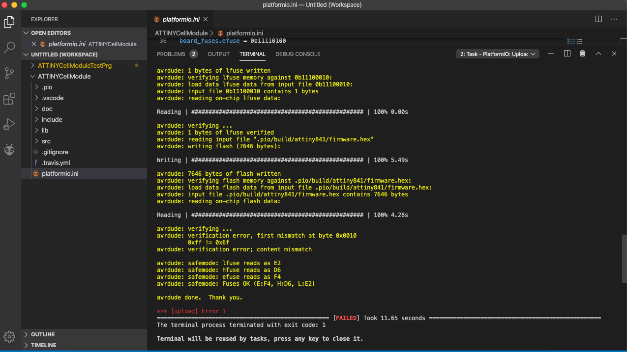
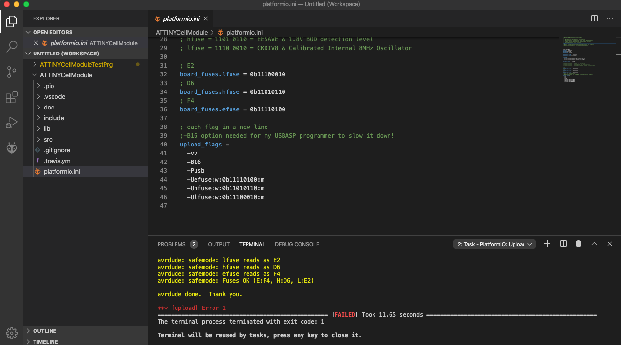
I am using an USBASP and don’t know what I am doing wrong.
Can someone help me with this.
Thanks
@stuart first, also from me wow you did an amazing job its great fun to deal with this DIY BMS. I build one set of V4 already by myself and it ran my little solar powerwall so far. Yesterday i find this thread with the talk about the pre assembled boards and it fits perfect for me because i start a new project and need a new set of those so… swapped to jlcpcb and ordered the V4.21 pre soldered save lot of time and money!
now to my idea i had trouble because my wife overloaded the powerwall with the waterheater and hat running 2 pc aswell as the TV, my cells are fused with 0.5A glass fuses so what sould i say? it lasts 1 sec. and boom all lights out =/ i checked the cell banks and at 1 from the 7S hat all fuses blown off light went out because my inverter EASUN works only with batt input and with 6S the V is to low.
okay at this point the V of the other banks pass the short way of the one with the broken fuses (main - and + that goes to the batt input of the cell module board) this burn also the module it went warm but works for now as a simple “cable”… i repaired all the things and it works again had to build a new module -.- but okay everything is fine again. out there are SMD fuses with little holders you can swap like a car fuse i was just thinking of mod the layout at the bat input with one of these only to secure the board from some stupid failures.
Hi, Is this all the parts i need to order for the controller and the modules?
https://github.com/stuartpittaway/diyBMSv4/blob/master/CellModules_LCSC_BillOfMaterials.xlsx
thanks
@BerndDasBrot I also have a home made powerwall with 0.5 amp cell fuses. I have also accidentally blown loads of them and had to solder them all back on to the cells again. So now I put a big fuse on the whole pack that is less than the value of all the 0.5 amp fuses and in this way it should blow first rather than all the 0.5 amp fuses. It is a lot easier to replace a single large fuse than all the little ones. I am also using a standard cheap BMS in combination with Stuarts BMS to provide the low voltage and over voltage protection.
This might just be a bad board. One of mine does almost exactly this and I can’t get it to work no matter what I do. All my other boards were fine though. Have you tried a different board?
@Stapes24 I think that BOM is just for the Cell Modules, it doesn’t include the Controller. It also may not include the little 2 pin connectors and wires you will need.
Thanks nick
Thanks Nick
I have tried to flash 3 boards and I have the same result. I have ordered the boards presoldered from JLCPCB and added the ATTINY and another component myself
Does any one have a BOM file for farnell in the uk for the module and controller?
I think if you scroll back a bit at one of my previous posts I give a link to a branch of the project that has the BOM file for the controller.
That’s what I did, though I only had to add the ATTINY and the connectors. Mine were all OK except for 2 that the ATTINY died completely (probably due to my soldering) and 1 that behaved like yours, almost like the internal flash of the ATTINY is bad or something. Perhaps @stuart might have a better idea?
Has anyone tried to swap out the NTC with a NTCS0603E3103FMT ?
I happen to have some of them in stock… They are 10K instead of 47K, but can you adjust that in the software? The NCP18WB473J03RB is a bit hard to find…