Yes, unfortunately it does.
![]()
Really, what a nightmare. I currently have boards in SMT production. The I went SMT assembly as I didn’t want to do it myself!
Really sorry about this, the two parts are very small, but that also means they are easy to undersolder and swap over.
The boards work as they are, but the thermistor is far away from the balance resistors - as a work around you could lower the balance temperature to a much lower value - like 45 degrees C instead of moving the parts
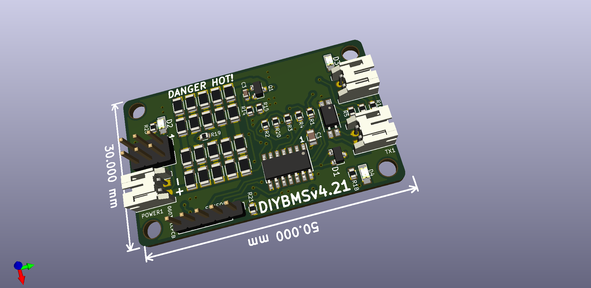
The fixed boards are now in GITHUB in the v4.2 branch. The new boards have a V4.21 silkscreen version.
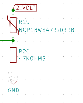
R19 and R20 have been swapped and the tracks updated to reflect this. The Gerber and CPL files have been updated and checked by uploading to JLCPCB.
Thank you I appreciate the prompt response. It’s reassuring to know that things will still work and there is a workaround 
If you’ve had to update tracks as well, will just swapping the R19 and R20 on my v4.20 boards work?
The tracks were moved to keep the circuit the same however, if R19 and R20 are swapped over on the existing v4.2 boards the components are still connected correctly (just upside down) if that makes any sense - its a simple resistor divider circuit.
1 Like
Yep, understood. Thanks.
Stuart
Thanks so much for this DiyBMSv4 project. I have been a long time follower and have benefited greatly from comments/questions of others and your answers. So I thought I would try to contribute a little by explaining my variations on your excellent work.
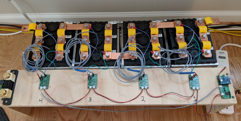
I’ve assembled the version 4.0 modules and controller for a new 300Ah LiFePO4 house battery for my sailboat. The picture shows my test setup. The battery uses 100Ah cells in a 3P4S configuration. I have top balanced the cells and plan to use them in the “linear” range away from the voltage “knees”. I’m using the DiyBMS4 for monitoring with Influxdb/Grafana and cell/pack protection control. Therefore I have not included the cell balancing features on the cell modules. To allow temperature monitoring of all 3 parallel cells in a group I have added a second external temperature probe to each module replacing the internal board thermistor. This second external probe is connected between pin 2 of the sensor header and pin 3 of the program header. I have also modified the controller code rules to test both temperatures to trigger relays.
The plan is to use the controller to drive protection relays for both high and low voltage/temperature events. However for low and high voltage events the relays will likely “chatter” because the disconnect will likely resolve the trigger voltage causing the rule to activate. To resolve this issue I have modified the controller code to incorporate a user defined cell and pack voltage hysteresis. So for example if a low cell voltage triggered a low voltage disconnect relay the rule would not reset until the cell voltage increases to the trigger + hysteresis voltage. This way the relay will not reset immediately on disconnecting the load. I use the same hysteresis voltage for the high and low condition. I do use a different pack voltage hysteresis value.
Thanks again for the great work and for sharing with the community.
2 Likes
Nice work @Jay_cd33, are you using the latest controller code? I switched that to using JSON payload for the MQTT data - or are you using the native Influx API?
1 Like
Stuart, I am using almost the latest controller code. I used the code from just prior to the changes you made to fix the compiler warnings. I did get those compiler warnings about “reply”. I am not using MQTT. I am feeding the data into Influx API running on a RPi.
@stuart @BuffaloPowerWall Really interesting. I found the pins, but what do you mount them in?
On a different subject, I’ve looked for an alternative to soldering wires directly onto a board. Something like a solitary pin I can solder the wire to and then solder that pin to the board. I wonder if you know of anything like that.
I just forced the pins into the female programming header with some needle nose pliers.
1 Like
I was a little more creative with the pogo pins, built an adaptor board and soldered them in place.
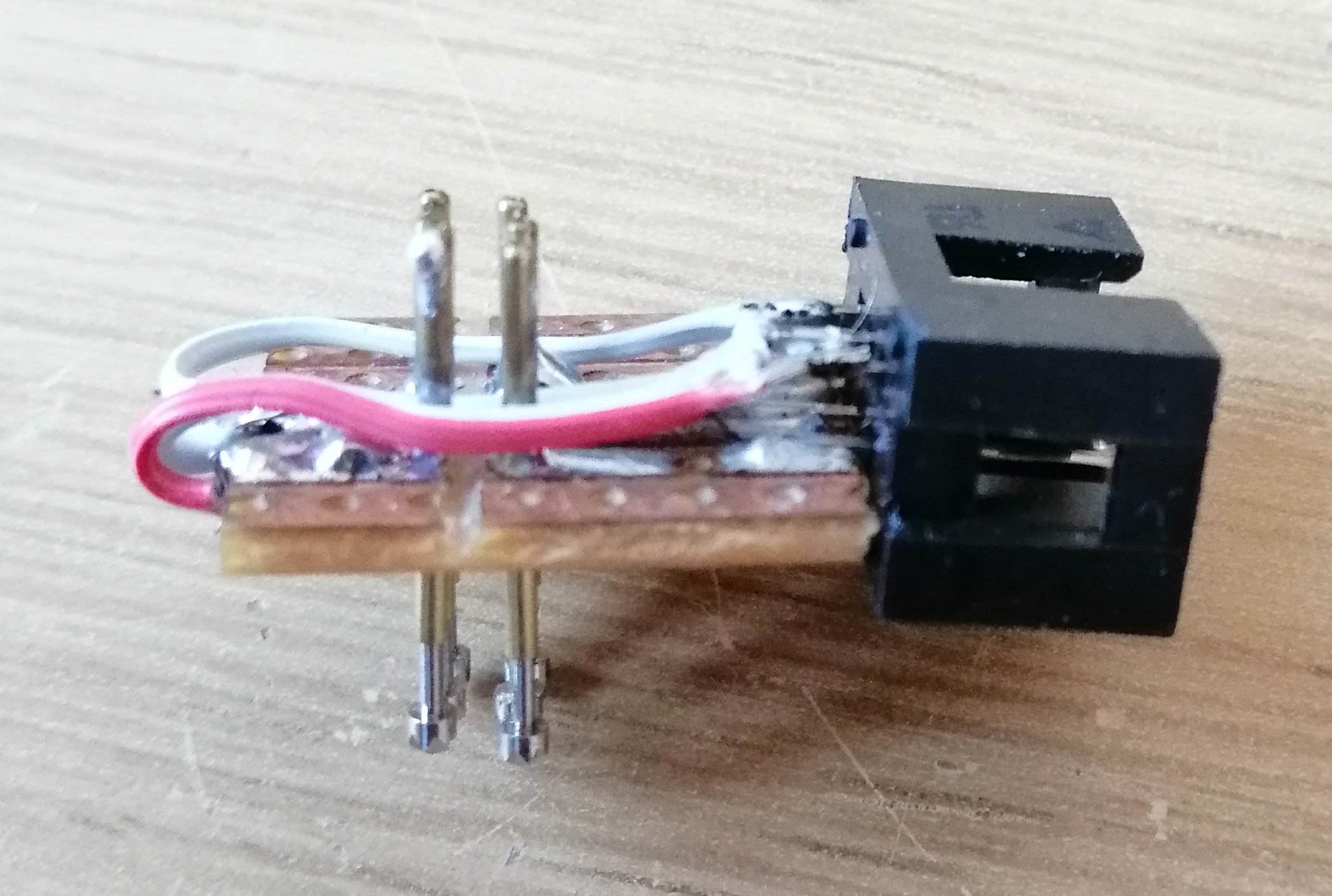
Not pretty but does the job. I didn’t have any 6 pin female sockets otherwise I would have done what @BuffaloPowerWall did!
@borpin for your wire to board mounting how about a ferrule ?
https://amzn.to/39jvM2u
2 Likes
@hotear I’ve tried the swap of R19 and R20 - it sort of works. Its REALLY difficult to hand solder 0603 parts!
I forgot that the temperature would invert so (it reads 50 degrees at room temperature and then goes down as temperature goes up).
For now I would recommend leaving the thermistor where it is and lowering the balance temperature.
If there is interest I can modify the module code to compensate for the inverted temperature if needed.
1 Like
Might do but that link borked ![]()
Looking good,
Can you explain how you made your programmer.