Which version is the best currently available for purchase as semi/fully-completed boards from JLPCB?
I was reading about 4.2, now I see 4.3 boards above, and on your Github you appear to have 5.15 … which version should I be looking at to order from JLPCB as completed boards? I want to minimize the amount of soldering I have to do myself.
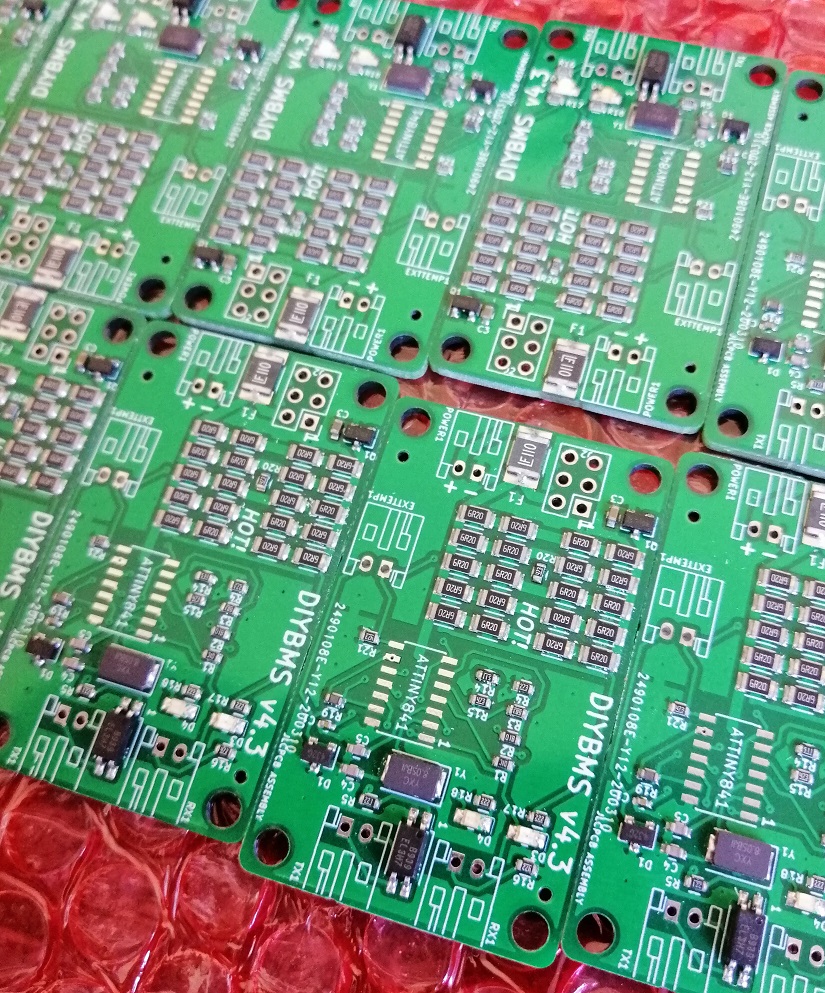
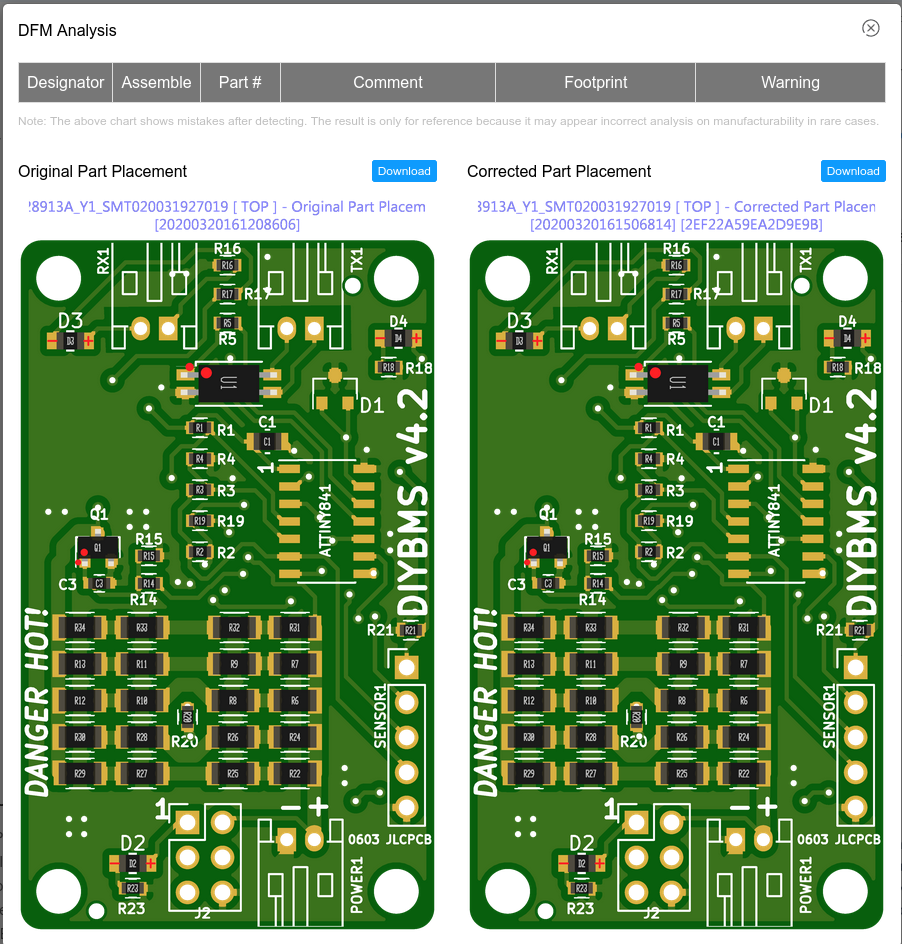
Have been following DIYBMS for a while now and ordered the 4.2 version through JLCPCB. I recieived a message from the engineers about polarity of some items, see below image.
In hindsight I should have cancelled the order and go with the 4.21 version, but the order is now assembled and shipped. I expect it to arrive in a few days.
Actually looking at LCSC, they do have the ATTINY. But they don’t have the 2.0V shunt voltage reference. They do, however, have the 2.5 (LM4040BIM3-2.5/NOPB). If the circuit could be modified a bit to use this one, then all the parts would be available from LCSC.
The advantage of this is that, if the Kicad files are uploaded to EasyEDA, assembled boards could be ordered. They only charge for parts, assembly is free.
@stuart would you consider doing that? Perhaps the part could be switched with only software changes? Or perhaps use a voltage divider? I’m a software guy, I’m weak on hardware but it seems this could work, no?
Or, perhaps replace that part with a TLV431AFTA? Not a direct replacement but LCSC has this one as well.
I’ve already done an LCSC pre-assembled board - take a look at the 4.2 branch in github. This has all the parts (except the ATTINY) pre-assembled by JLCPCB (who use LCSC). No need to manually solder the tiny parts. The board version you want will be labelled 4.21
Is there no way for you to be able to load the board/parts as a standard build with LCSC that others could then use? Could make life easier. Does it run into the the ‘you can sell completed boards’ rules?