The default is 1.6 so I’ve gone with that. Just checked on the order and it “failed the audit”
Error is "audit failed reason:
Hi Sir/ Madam, there are too many files in your zip file and we don’t know which file we should use, so could you please delete useless files in your Zip file?You can click ‘Replace file’ button to re-upload the file in your JLCPCB account page .Thanks."
I’ve never used a service like this before so I’m all at sea. I uploaded the github v4.2 zip file to generate the order. I’ll be happy to document this procedure for the next pilgrim to come this way.
I should have mentioned I’m putting together a powerwall with a couple of hundred 18650s powered by 5Kw of solar. I’m currently off-grid via petrol generator and am aiming for a solar/wind hybrid system. Current global events leave me with the time, resources and inclination to bring this to fruition.
thanks again for the boards and all your work you have put into it.
I have soldered on the remaining pieces and got the setup working, currently with a 20s3p setup and planning a 60s7p configuration.
I think using ethernet instead of WiFi, as the WiFi connection in my basement is very bad.
The (W5500) ethernet modules require an SPI connection. The MOSI/MISO/SS Pins of the ESP8266 are used for the communication with the cell modules by the Serial.swap in the code- The standard TX/RX ports are on pins 7 & 8 in the circuit and are unused. What was the reason for the swap?
Serial1 is used as debug channel, but could not see anything via USB.
Do you think, it will be possible to switch the serial communication back to normal TX/RX pins by removing the swap? Do I have to disable the debug output as well?
The problem then is the usb connection to the esp is also connected to all the cell modules.
When you program the esp it will send all that data over to the modules, most likely causing problems. You could obviously unplug the modules first, but for safety I built it the way it is.
ive gone ahead and ordered some for my nissan leaf setup, thankyou for adapting stuarts layout to make it quick and easy for the leaf cells, i already run v4.1 on my leaf but will give these a try when they arrive.
are the jst connectors you mention are they ph2.0 or 2.54 pitch?
I had, have corrected it and it went fine. I don’t know what was in my head vis a vis letting them build the board, it really is cheap. They had all but 2 components, the ATtiny841-SSU and the AZ432ANTR-E1. This is for an S13P9 powerwall, to start with anyway. Thanks for your help.
Hi guys, waiting on my 2mm crimps for the JST connectors. Finished assembling the module board but since I can’t connect the TX RX yet I was wondering if you just connect the module to a battery will any lights flash up or do you need to provision them first having them all connected. Just wanting to check if I’ve done a good soldering job.
You can program the attiny chip and it should flash the green and blue LEDs then every 8 seconds or so the green led should flash.
Before you do anything though just check the resistance between the positive and negative connections at the power input, this shouldn’t be a low value otherwise you have a short circuit!
I’m having trouble finding the wemos board i have ordered several and the all are only 4mb I’m in the USA and have been looking on amazon. does anyone have a link to a know good seller her in the USA. the module is all i have left and would like no to have to wait 3 weeks on it if possible.
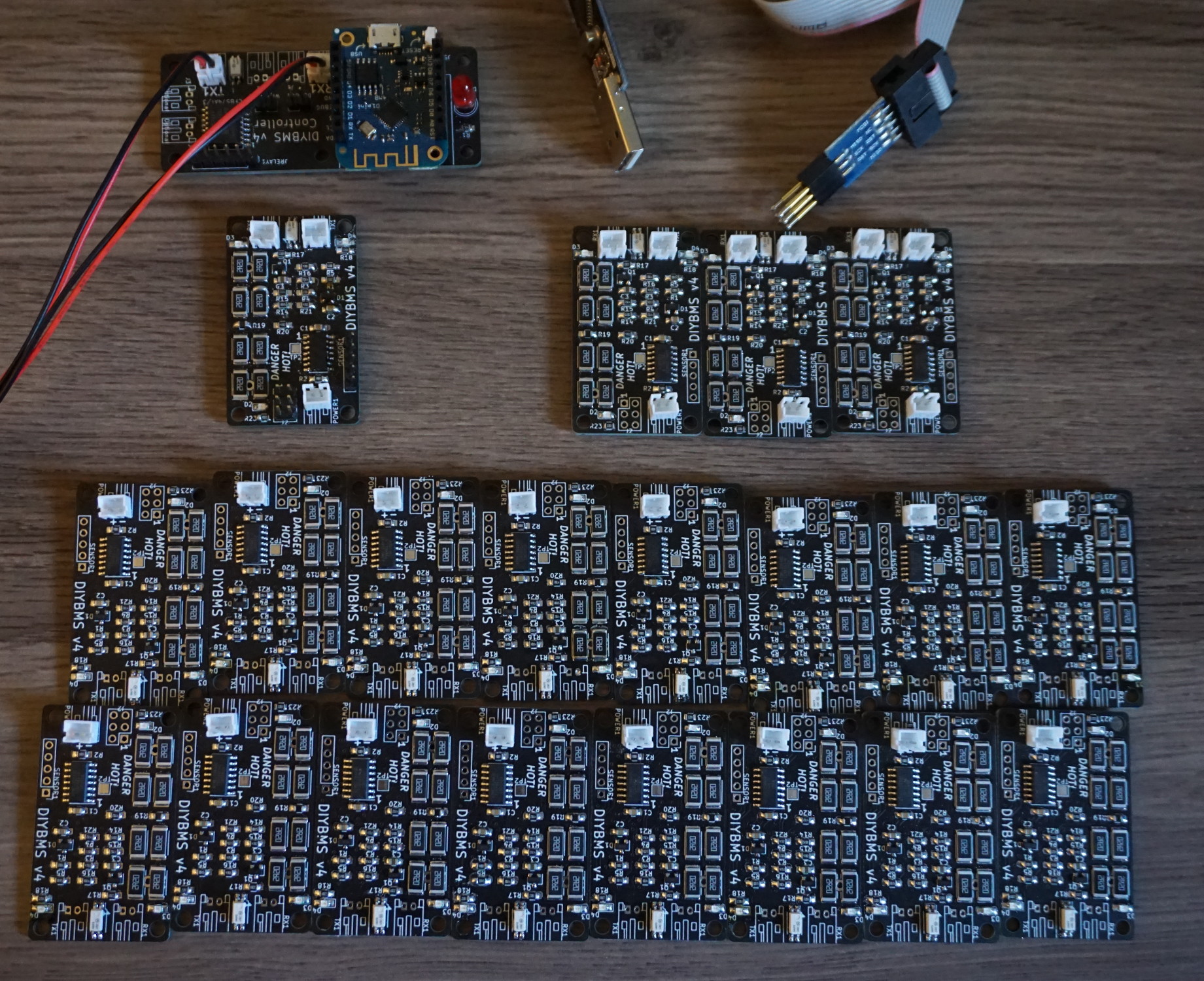
Nice work - you hand soldered 0603 parts ?!? Crazy
I also use the pogopins for programming - saves soldering a connector on the boards - its a shame it takes about a minute to program each board though as my hand hurts holding that long!
Just reporting in after being silent for a long time. Rain here and cloudy for ever it seems, so my batteries have been just sitting on top balancing. They are at 4mv difference.
So, I can program both controller and boards to get the new software going? I’m quite happy with my current setup though.
Thanks again @stuart for your design and work on a great project!