DIYBMS v4 Shunt Design and discussion

@atanisoft The ESP32 would eliminate the need for the PCF8574, right?

I assume that the software changes would be tedious, but no big deal.

The ESP32 seems available on JLCPCB (I mean it was in the easyeda library). But, I’m not sure it makes sense to make controller integrated with the esp32. If you end up buying 5 of these boards from jlcpcb, then isn’t the daughter board cheaper?. I suppose not if you could sell the extras.

I am tempted to go this route but I would do the following:

  • 3x TLP22A-2 for a total of 6 relays
  • 2x INA226 (1 for main battery, and 1 for PV)
  • at least 2x inputs (I use them as switches to turn on/off the loads)
  • Use the JLC connectors S2B-PH-K-S because we end up buying a bunch of these for the modules. 4x for each INA226, 6x for the relays, and 2x for the inputs
  • Some opamp circuit so that the pack voltage > 36V can be sent into an ADC. Maybe the user will solder in the appropriate resistors to handle their particular voltage. The INA226’s can be used from low side shunts on any voltage pack. Stuart mentioned that having the pack voltage would be a useful thing for the rules.

I would be looking at using a socketed ESP32 ready made board - probably ESP32-DevKitC-32D which most people can get hold off, is a standard design/pin out and stocked at major global parts suppliers.

1 Like

Can you give me the examples of what you would be controlling with up to 8 relays?

  1. Switch on/off charging side (overcharge protection or other rules)
  2. Switch on/off load side: main inverter (overdischarge protection or other rules)
  3. Switch on/off load side: critical loads inverter (overdischarge protection or other rules)
  4. Battery cooling (cell temperature too high)
  5. BMS cooling (cell module too hot during balancing)
  6. Battery fully charged (signal for external system that battery is fully charged and extra solar power could be used for additional purposes, for example water heating)
  7. Battery heating (cell temperature too low for charging, might be useful for LiFePo4 if temperature in the battery shed is below 0 deg C)
  8. Reserve (for example battery cooling stage 2)

Now that I have written this example, one more thought about rules arose in my mind.
Now we have a list of rules with a possibility to activate relays, if the rule is “true”. But it would be more flexible to have a list or relays and have a possibility to activate rules for every relay. So to say: to switch columns and rows in the table.
I do not know if I explained it correctly, but here is an example of logic
Now:
IF Rule_1 = TRUE
THEN Relay_1 = TRUE; Relay_2 = FALSE; Relay_3 = TRUE; Relay_4 = FALSE;

My idea:
Relay_1 = ( Rule_1 is TRUE OR deactivated) AND ( Rule_2 is TRUE OR deactivated) …
Relay_2 = ( Rule_1 is TRUE OR deactivated) AND ( Rule_2 is TRUE OR deactivated) …
and so on

*probably an “AND/OR logic” selector would be required, but I am not sure

In this case the rule Overvoltage, for example, could be used for every relay with different set points. So generally we will have much more flexibility.

Practical example for the list of 8 relays above:
Relay 1
Function - Switch on/off charging side (it is not fixed, it could be any function, I have written it only for better understanding of the idea. However, in the web interface it would be nice to have a possibility to give names/function descriptions for relays)
Relay is on (charger is on) if:

  • individual cell voltage below set point
  • individual cell temperature below set point
  • no emergency off signal

Relay 2
Function - Switch on/off load side: main inverter
Relay is on (main inverter is on) if:

  • individual cell voltage above set point
  • individual cell temperature below set point
  • no emergency off signal
  • battery total voltage above set point (lets say 47 volts for a 14s pack)

Relay 3
Function - Switch on/off load side: critical loads
Relay is on (critical loads inverter is on) if:

  • individual cell voltage above set point
  • individual cell temperature below set point
  • no emergency off signal
  • battery total voltage above set point (lets say 42 volts for a 14s pack)

And so on.
As you can see, for Relay 2 and 3 a similar rule is used, but with different values. With current rules, a new rule should be added for such functionality, but if columns and row are switched, then a separate sep point would be available for every relay for every parameter (like “voltage higher than” for every relay, “voltage lower than” for every relay, and so on) , which give us much more flexibility in configuration.

What do you think abut such suggestion?
1 Like

Nice this makes sense, So those who don’t need it don’t need to buy it… I like it !

If you go for socketed I’d recommend the PICO-D4 DevKit rather than DevKitC.

Yes, the ESP32 has a number of IO pins available that are free to use for most purposes, keep in mind that they have a limit of ~15-20mA current available to them. It is sufficient to drive LEDs and very likely relays as long as they are active LOW (current sinking capability is higher than current sourcing)

There may be other reasons to include an op-amp than just supporting 48V packs.

As noted above, I’d likely swap this for INA229 which supports up to 85V. I’d also argue against the need for PV to be monitored by the BMS system, that should be the responsibility of the charge controller typically.

I disagree, a LiFePo4 pack does not need a charge controller. The max power point of a 60 cell panel is very close to 27v of a 8 cell LiFePo4 pack. So all you need is a relay to turn it off from the BMS and a diode to prevent current from draining at night. The DC/DC converter in the MPPT is going to waste energy most of the time, in the hopes of an insignificant gain when the stars are aligned.

I have 8p2s 36 cell panels to my 24v pack, so I could achieve more power with an MPPT, but I’m not about to buy one. I’d rather swap my panels for 60 cell ones if I needed more power. I’d rather make sliding drawers on my RV roof to hold more surface area than waste money on an MPPT.

I don’t see anything about INA229 above. It is surface mount, but I don’t see INA229 on JLCPCB, and I don’t see a breakout board. Why not use the cjmcu-294?

But I would still use the INA226 for the PV. It’s nice to know what you are getting from the PV in an RV.

It has the same footprint as the INA226, VSSOP-10, it might be a little challenging for hand soldering but it should be doable. Likely the most challenging part of it would be the 0.5mm pitch on the pins, but even that the drag/cleanup approach should work.

I’m not finding that part number on JLCPCB or Mouser. The only place that matches is a battery temperature sensor board of some sort and those appear to be limited to 60V.

Then we will agree to disagree on this one. There is definitely more than one way to implement the system.

I agree, usually this is available via the charge controller. But in your case you are opting for not having a charge controller so you would need some sort of meter on the PV side.

I would still suggest using the INA229 even for PV since it would allow you to go higher on the PV input in the future if/when you move up from 24V to 36V or even 48V.

Google for the CJMCU-294. It is a breakout board for the ltc2944, which will accumulate the amps to provide a state of charge. I think the self surface mount nature dramatically reduces the appeal of the DIYBMS. When I discovered that the module could be built by JLCPCB including the ATTINY, I went for it.

Why would we disagree? This is an engineering matter with facts and measurements, not religion. What am I missing? It does not seem logical to leave out an additional INA226 because some might already be getting their PV info from an MPPT. Many will comprehend the waste of an MPPT and want the PV info from the BMS and will be controlling their PV from the BMS.

The marginal cost of another INA226 is what, $2?

I don’t have a problem if several different controllers are provided on DIYBMS, except that everyone ends up buying 4 extra. If the single design can handle a huge range of use cases, then each of those extras are more resell-able.

Why? Just put the PV shunt on the low side.

The only reason I am putting my shunt on the high side is to get the whole pack voltage, and that is a rather useless thing anyway. The controller already adds up the individual cell volts. The rules need to be updated to do something interesting with the situation where the modules do not add up to the pack voltage. I’m not sure what failure case this would be, except maybe you have a bunch of poor bus bars.

The point is that you only need one thing to measure the overall pack voltage. All the current measurements can be low side, and thus there’s no need for high volts. If an opamp can be made where the user solders in the appropriate resistors for their pack size, then the design, including the INA226, can handle any pack size.

Not all battery packs are made from the same chemistry and some people prefer to have a charge controller. In your case you have opted for not having it and that is fine as it is your setup.

Agreed, it needs to be generic enough to support the common user and more specialized cases.

Sure, but having an overall “battery” voltage on the output end would be useful for the case where you have more than one string of batteries hooked to the same diyBMS controller.

Usecase: two sets of 7s80p with one controller. Modeling this on the controller can be done in a few ways, two of which being: one bank (14 “packs”) or two banks (seven “packs” on each bank). Since the current controller is limited to four banks it would be advantageous to have a single bank in use since you can in theory have up to eight sets of batteries being monitored (56 individual “packs”) whereas splitting each 7s80p into a dedicated bank means you can only have up to four sets (28 individual “packs”).

Now, with moving up to the esp32 maybe it would be feasible to model this more dynamically to expand the number of “banks” to more closely align with the actual layout of battery packs without the limit on the number of “banks” in use today, though that may require a tweak to the communication protocol to add an extra bit to the banks field.

You seem to be missing the point. I am not arguing that everyone must take advantage of the 2nd INA226. You are arguing that everyone will have an MPPT, thus nobody will want the 2nd INA226 for measuring PV current. My point that the MPPT is a waste of money is to make it clear that I won’t be the only one to understand this and thus there will be many DIYBMS users that want that 2nd current measure.

That’s all fine.

I am still arguing that the INA229 is a poor choice. The overall pack voltage can be measured with an opamp going into the ADC on the ESP32 enabling any pack voltage by choosing the correct resistors. This would be more flexible because it is not limited to 96v, and does not have to be soldered by the user.

The 2x INA226, supplied by JLCPCB, can be used to measure current for any pack voltage with a low side shunt.

The amps and volts don’t need to be measured by the same circuit.

I think actually we are both after the same goal, flexibility in design. The end user can decide between either the INA226 or INA229 since they have the same footprint. Similarly they can choose to have an MPPT or PWM controller if they want that.

Do you have a circuit in mind? I’m curious on how this might look on a schematic.

Agreed, an external sensor (even a CT) would work quite well for measuring the current going in/out of the packs. A CT may also not require any specialized hardware on the PCB, just an ADC pin and a bit of calibration via code.

An opamp is needed to amplify the delta voltage across the shunt and I was confusing that with the VBatt, so never mind about the opamp.

Why not use a 2 resistor voltage divider? I apologize, but I don’t really understand the risk of a non-isolated battery voltage going onto the controller. The high side resistor could be a few resistors to eliminate the risk of a shorted resistor. This would require that the controller share the same ground with the battery, which is not a requirement with the current controller.

I’m not enough of an expert to know whether this is a big deal or not.

I like Stuarts plan to make a shunt ammeter that is isolated and will plug in, and therefore one could get just the set of modules that are required for one’s needs. However, you get 5x of anything you buy from jlcpcb, which put’s a damper on that fun. So I feel the idea should be to load the controller with everything but the kitchen sink and resell them.

Do you know what the differences are? Is the PIN out the same?

From a functionality standpoint, they are virtually identical. The DevKit-C uses a PCB Trace antenna where as the PICO-D4 uses a 3D antenna.

Aside from the antenna there are a couple differences between the two DevKit boards:

  1. The DevKit-C uses a 25mm pin spacing on the two rows of headers whereas the PICO-D4 is roughly 17.5mm.
  2. The length of the DevKit-C is 54mm (to end of PCB trace antenna) and PICO-D4 is 52mm (to PCB edge).
  3. The PICO-D4 omits pins for CS,D0,D1,D2,D3,CLK whereas DevKit-C provides these. These pins are not user accessible pins (pins 6-11) as they are directly connected to the on-board flash. Attempting to use them WILL result the esp32 crashing in most cases. Therefore the PICO-D4 is safer in this regard.

Overall it is a newer variant on the DevKit, silicone and safety features for the end-user.

I agree, having the shunt and related hardware in an isolated fashion is very desirable and offers a lot of flexibility.

The only problem I see in not having isolation is the ESP32 is very sensitive to the voltages supplied to the IO pins. The ESP32 datasheet (all variants, not just the seven listed in this one) lists an absolute maximum voltage rating of 3.6V DC. The ESP-IDF documentation for ADC attenuation lists 3.9V as the full-scale voltage maximum but it is in fact limited to VDDA which has a range of 2.3V to 3.6V (section 2.2, page 8 of the datasheet).

That should be fine as long as the minimum voltage output is at least 100mV (lowest the ADC will detect). Anything below that will either read inconsistently or even read as zero, both of which are not ideal.

Sending the full scale battery voltage through a shunt and feeding the output to the ADC (with or without an op-amp) might just work. However, using an INA226/229/etc would be a better though as it is a purpose built IC that does not suffer from the inaccuracies that have been observed with the ESP32 ADC.

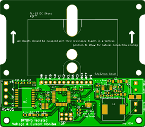
I’ve sent off a prototype shunt design to JLC, this is using an isolated RS485 comms and the LTC2944 “battery gauge”. No idea if its going to work yet!

2 Likes

I’d say your design looks pretty good. A couple minor comments:

  1. adjust your GND fill to be solid where it connects to pins so you have a stronger connection to the pins (see the BAT NEG terminal on right side has spokes)
  2. double check the traces have sufficient clearance on the QFN like IC, specifically top side left corner they look just a tad close to the pads.
  3. double check that all components are sized for thermal dissipation needs (I think they are but would need to see exact components used).