If I’m going to swap to ESP32, I wouldn’t keep the 8266 as well, it just adds to the overall cost/complexity and is another device to support and code for.
Not into the original board no, there just aren’t enough data pins on the ESP8266. I can probably free up a couple of pins for another software serial port to communicate with the shunt device, but would need a redesign of the controller PCB.
If I’m going to redesign the controller PCB, I may as well migrate to the ESP32 at the same time - which then removes the need for the PCF expander chip, so reduces costs there.
Just to update on current thinking for an isolated shunt.
My initial prototype is likely to cost about $40-$50 USD which includes the shunt, dedicated shunt controller board (using RS485 and isolated voltages) and includes voltage measurement and current measurement, and energy counting.
Its likely that a new controller board would be needed - probably around $10 USD and ESP32 - again about $10 USD.
Does this cost seem high/unacceptable ?
3 Likes
All that would beed to happen is the New esp32 controller would import the data from the esp8266 controller and display this on the web page.
Thus the new esp32 controller + a separate esp8266 controller would allow upto 128 modules together, and utilizes hardware we already have. It would also allow progressive expansion.
If I used a new esp32, I could have two or more serial ports for the modules to connect to, so 128 modules could be driven by a single ESP32.
Do we really need so many?
The only problem with having 4 banks in one string is that if communication fails, or a module loses power all 4 banks stop working.
From a safety standpoint having each bank or even 2 banks to a string reduces the likelihood of total comunication failure.
You also mentioned before that the time it takes for the data to be passed along 4 banks is a problem.
So by splitting up the workload we increase safety and utilize hardware we already have.
I have plans for 5 or 6 banks myself, maybe more. I did think about making it as 1 big bank using balance wires, but id rather have easy maintenance and individual cell monitoring.
The Batrium shunt sells for ~150 USD, so 40-50 USD is a very fine price ![]()
And 10+10 USD for an ESP32 controller, that is more future-proof, is also very reasonable in price if you ask me
2 Likes
IMHO, it depends on the scale. For example for me (3 banks: 14s120p) it is perfectly fine, but for smaller scale (like 7s20p) it might be a bit too high. I do not know if we have too much people who use “small” batteries, but personally, I like your suggested design and wait for the release =)
Not to me. There seems like a lot of open space on the board for a re-work of sorts, so purchasing a couple of new controller boards and parts would be fine.
Being an in-progress project as this is, having one controller board capable of handling all (or most all) the future accessories would be great.
I would have to say that having a diyBMS v4 controller board light and a full version would be nice. The Light version would be what it currently is.
Has anyone thought of using a Hall effect sensor with a differential amplifier? (wiki)
1 Like
Yes - if you scroll up the forum a bit mnm1501 mentioned it a day ago.
Thanks Stuart, missed that.
I’ve upgraded from v3 to the v4 board and am VERY happy with it. It does what I need it to do, and it does it perfectly. I think that a non-contact type of current sense would be best for diy-ers. If you upgrade the controller board, I will build it…
Speaking about ESP32, if we have more serial ports, we could make a shunt module and using the same hardware/software, send data to the ESP32 main controller (optocouplers, serial data,…). That way it will be also isolated from everywhere and will be cheapest as with could build it with a pro mini, or attiny.
We can build a shunt “module” with a LTC2249 (INA226 or whatever, it will not be important if it has a I2C isolated or not) and a pro mini/attiny with I2C and pro mini/attiny speaking with USART to ESP32 main controller.
It could be possibe?
I guess the question is what would the cost of a new controller be which allows you to read from a shunt, versus a dedicated shunt PCB which send data to the controller board.
I don’t quite understand the deal about isolation, shunt resistors send mv down a wire to the controller the controller knows the bank voltage and reads the mv and we set the resistor detains, then calculates the current, how would the shunt send 48V to controller if this is through a resistor ?
I guess people who will be spending money on the shunt would not mind upgrading their controller ? and this controller would then become the new default controller with the ESP32.
DIYBMS v5 ? wouldn’t this then allow you to moudlize ad-dons, not sure what else you could add to the project, but if you had a separate Shunt PCB that would carry a higher cost and one you could add to a new controller, then when the next project arrives and we still have the old controller this again would end up standalone and higher cost again rather than an add-on to the new controller.
I suppose you should consider the end goal what would work out cheaper if someone new came along and built all the projects if each had their own dedicate chips versus and expansion type desing ? Look I am not familiar with all the costs of these things but I suggest trying to keep the controller “the brains” always the controller and then just build expansion boards, and if the current controller is not up to the task then its ready for an upgrade. the end of the day the current controller is not the cost of the operation its a few $ its the 28 modules I have to buy, so replacing the controller is a non issue in my opinion
I had designed a PCB to replace the current controller with an integrated ESP32 SoC:
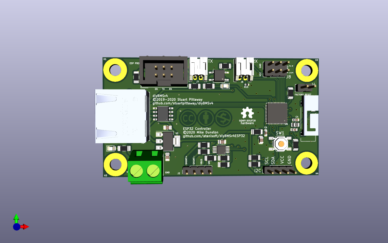
A quick rundown of features on the PCB:
- ESP-PROG header for ease of programming.
- CAN transceiver for connecting to solar charge controller (was planning on EPEver/EPSolar).
- Integrated INA-226 with header to connect a shunt.
- External power connection with 3v3 buck converter to power the ESP32.
- Nearly the same footprint as the current controller PCB (40x75mm).
- I2C header exposed for expansion (ie OLED/LCD display).
At the time I designed this all parts were available via JLCPCB except the antenna, unfortunately they have stopped carrying the ESP32 for their assembly services. The approximate cost for five populated boards was around $55 USD (plus shipping of approximately $18 USD) or for 30 boards it is around $116 USD.
If there is interest in this I’d gladly refresh the design and share the files with @stuart or others.
Looks great but I understand nothing about these components, however if the ESP32 is not available from jlcpsb then that would be a problem as the component is hard to solder ?
I wouldn’t attempt hand soldering of a QFN-48 part with an iron, especially not on the ESP32-PICO-D4 as it has 49 pins (GND pad on bottom side) and the side pins do not have much exposure for hand soldering.
If I revisit this design I’d swap for either an ESP32-S2-WROVER module or for the ESP32-S2-Saola-1 devkit. Both of which have more IO pins available and native USB support.
It would only be possible via stencil and reflow oven/hot air.
I made a new controller board that has 2x INA226 current measuring chips. I will use one for main battery State Of Charge, and the other for PV amps. The INA226 will only handle 36v. My pack is 8x LiFePo4 (24v).
The new controller has 4x opto isolators (2x TLP22A-2) that handle 500mA, that I will use to turn on/off inverter, DC/DC converter, charger, and PV.
I have updated the software to use one INA226. The image is showing my test setup where I have a 13.38 V power supply, a 500A - 50mV shunt, and 30ohm load. As far as I can tell it is working fine. The SOC dropped to 10% after 2hrs where I set the battery size to 2Ah, so that seemed accurate.
I am doing a simple .5 second interrupt to sample the amps and accumulate that into the SOC. The “ticks/hr” is telling me that since it booted, there’s been an average of almost the correct 7200 samples per hour. I wanted a feel for whether I should bother attempting to factor the timer inaccuracy into the calcs. I figure no. The SOC will be set to 100% when the controller shuts off charging at 3.5v, and that wipes any accumulated error. On boot the controller does not know the battery SOC, so it assumes 50%. Since the solar will bring the batteries back to 100% most every day, I don’t think I care to eeek out better accuracy.
Issues:
- I have no great skill at circuit design, especially with respect to isolating signals. I don’t really know how to determine if there are problems, much less avoid them. I tried to keep the runs to/from the INA226 as short as possible. I made a ground plane on both sides of the board, but I’m not sure I could tell a ground plane from an airplane.
- The 2x TLP222A-2 are not available from JLCPCB, but they are DIPS, so trivial to solder.
- I don’t know what to do with the software changes. I could commit them and they will not be noticed by anyone that does not have an INA226 chip.
- I’ll share the PCB design if anyone cares.
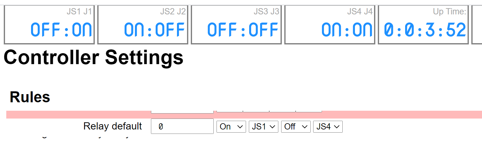
- I plan on implementing a feature where the J1-4 unused inputs can be used as a switch for the different loads/chargers. The UI will show the status of these and they will be included in the rules. The idea is that I can turn off my inverter with a switch mounted at the door of the RV, and the web page will show the status. I have not implemented the thing that will reset the SOC to 100% when the controller shuts off the chargers.
I am waiting for my new boards. The one I am using now had several problems.
Comments?

Nice work there. You mentioned that you only used a resistance load when you measured the SOC in testing, do you think a half second sample size will be enough for spiky loads that are not constant?
Are you planning to do anything clever with the SOC the commercial ones often have a wear profile built into them to cope with aging cells over time.
There certainly could be a repeating spiky load near the half second rate, or some multiple of that, that would make a joke of the SOC. I don’t think there is such a thing in my RV, so I am not too worried about that. Any random spikes should be insignificant for the SOC (I have 24v 280ah).
I assume that the half second rate is totally insignificant for the esp8266, but I have no feel for what is possible. I don’t have any intuition for how taxing the rest of your code is. I used no floating point values at all, so I figure the CPU load I added is nothing.
I suspect the the INA226 is capable of averaging over a short time. There is some feature that I have not spent the time to explore where you set the calculation time and are interrupted when it is ready. I am guessing that this is going to be sampling the current at some higher rate and averaging over the calculation time. My first board did not have that line connected, so I did not attempt to understand what is possible. My next board will, so I can experiment with it. But I could be totally wrong about what that calc time thing was about.
I am not planning to do anything with a wear profile. I have no clue how accurate this is, so it makes no sense to attempt more accuracy along those lines. The problem is that I don’t know what measurements to believe and thus no great way to judge whether any additional code is adding accuracy for simple loads. Anything that takes years to be measurable is right out. I have an electrodacus BMS that I can compare with, but if they are similar, which one is more accurate? I have no clue if he’s got some messed up code, or loads on his CPU, that makes his SOC less accurate than mine.
I don’t have a feel for the different use cases, but I suspect that mine is typical. I use PV and therefore 99% of the days, my battery gets full and does not come close to empty. Any accumulated error is wiped out when it reaches 100%. Similarly, when it reaches the bottom, we can judge how accurate the capacity setting is, assuming we believe INA226 and the code.
My plan was to install this in the RV, turn on 2 1500watt AC heaters, and watch what happens after about 2 hours (I have 24v 280ah). Hopefully it clicks off near 0%. I think I will put some code in there to report the discovered capacity. But, after this, I will probably never get down to zero.
I will also add SOC rules to the relay code. My settings will have inverter shut off at say 10% SOC, the DC/DC converter which powers the controller will shut off at low volts. Another relay will shut off the refrigerator and electric water heater below say 75% SOC (they both run on gas when no AC is present).
Indeed, that raises a question. I am going to power my controller with a buck converter powered from my DC/DC converter that will be shut down when the controller sees a cell at the min volts. This means the controller will kill itself, which is good. This should never happen, because I have PV. So if it does happen, something is very wrong and I would also like to shut off the modules. Is that possible?
After 2 deleted idiotic posts, maybe this one will be useful.
I made a change to the default rule such that the relay can get it’s value from the 4 inputs (I call them JS1-4, where the S is Switch).
I figured it would be handy to show the current state of both the switches and the relays. This particular display is not good. I think the future will have pretty indicator lights and the user will be able to name them so instead of JX, it will be “Inverter” or whatever.
1 Like
If you diced to move to esp32, maybe it would be a good idea to add also a support for more relays for rules (8 instead of 4)?
1 Like