Hi @John_Taves, @stuart
The LTC2944 is almost perfect from a feature point of view. The down side is the chip is not DIY solder friendly… a 3mm DFN with exposed pad would put hand soldering beyond the reach of most. However, look in AliExpress for LTC2944 and you will find small evaluation boards that could be repurposed.
The other downside is there is no easy way to run the chip with galvanic isolation, opto isolated I2C control. Mixing grounds, battery and the controller can give odd problems.
The LTC2045 has fewer features but does support isolation and can be had with small flat pack that is hand solderable.
Why not remove one of the 4 banks, and dedicate it to shunts. Therefore 3 banks of 16 cells and then bank 4 is for current.
Or keep it as is, but allow the controller to specify which module is a current module and it then reads the values as current not voltage, therefore using the same data as a cell module
This shouldn’t matter as i pointed out, whatever chip or chips on the shunt module used to measure the soc would keep adding to the cumulative tally, the data would then be read on the next poll. SOC will not charge dramatically in 3-4 seconds.
Probably yes. The existing design is limited (by the ESP8266) on the number of pins it has for interfaces. I think I can make it work with the existing ESP8266 devices so it would just be a controller PCB swap.
I’ll likely try and get a batch made and sell them via the forums shop so its easier for you folks.
If it works then i dont see a problem. But it seems a bit of a waste of the boards we already have. I have 5 as that was the minimum order, i dare say most others are the same.
However if we are to go down this route, would it not be a wise idea to maybe look into the esp32 to further future proof.
Also maybe the boards we already have could possibly be used as an expansion board, i.e. more banks of cells and pass the data to the esp32?
I was an idiot. I was forgetting that the ADC on the ATTINY is not going to able to measure < 50mV. It’s not a matter of accuracy, so much as the dynamic range of the delta it is capable of measuring.
My bad. I deleted those posts.
However, I still think that it would make sense to put this circuit onto the module board. It is doubtful that jclpcb has any of these chips to surface mount, so most likely we buy one or two of these and add it to one or 2 modules. There are a lot of single cell Coulomb accumulation chips that I ignored because they didn’t handle large voltages. We only need 1 cell of volts if it is mounted high side and any will work low side.
As I was writing this, snail mail spam arrived with an ad for this: Smart Current Sensor SSA - Riedon How ridiculously timely. This shunt will amplify the differential voltage signal and isolate that. It should deliver 1.2v @ 250A (for the 250A shunt), if I am reading this correctly.
@stuart Can’t this be sent into the unused ADC on the ATTINY? And wouldn’t that be enough range to get decent accuracy?
Is there any reason the ATTINY does not have enough CPU cycles to poll this and accumulate and deliver it to the controller on demand?
Will it be a problem to add this data to the communication protocol to the controller?
I suck at circuit design, but I can write software.
@John_Taves.
This is a nice system… but… For 250A shunt $70 shunt + $11base + $11 custom cable + shipping. $92+ and you still need a differential to single-ended opamp on a PCB to feed the ATTiny. If Stuart reworked the original ESPcontroller the opamp could be placed there. But you are back to have 4 unused controllers.
Damn, good point. I didn’t look at the datasheet in detail, I assumed it would provide a single ended output. My hope was that I could use this with an existing module (cell module, not the controller). My hope was that I could use this and implement the software to accumulate the amps in the ATTINY on the cell module and transmit that the the controller.
Are you understanding the idea that the cell module (not the controller) can be modified to collect the current sums?
I feel like Stuart and you have not really evaluated that concept.
For the shunt, I am hoping to build a device which would be generic enough that others could use it without DIYBMS - for instance by using modbus or CAN bus protocols to comply with off the shelf standards.
The existing code on the modules and the comms protocol it uses isn’t designed to carry additional payloads like shunt readings without modification. I’m sure it can be changed, but then you are also asking every user to re-flash the module code (and some are running with 30+ modules!).
It also doesn’t solve the isolation issue unless you run a seperate power supply from the battery cells. Just connecting a new shunt module to an existing cell will add extra drain on that cell and start an imbalance.
Using an ATTINY to calculate the current/power and SOC is perfectly doable, but I don’t have the time to spend working out the calculations and writing the code when a perfectly good custom chip is available to do it.
I would also want to measure the total pack voltage to compare that with the voltage the modules are returning, this then allows additional rules to be written to spot errors or potential issues.
I’m more than happy for others to build add on modules for DIYBMS (in the spirit of open source etc.) and write the code to support them - I’d be grateful for the GITHUB submissions!
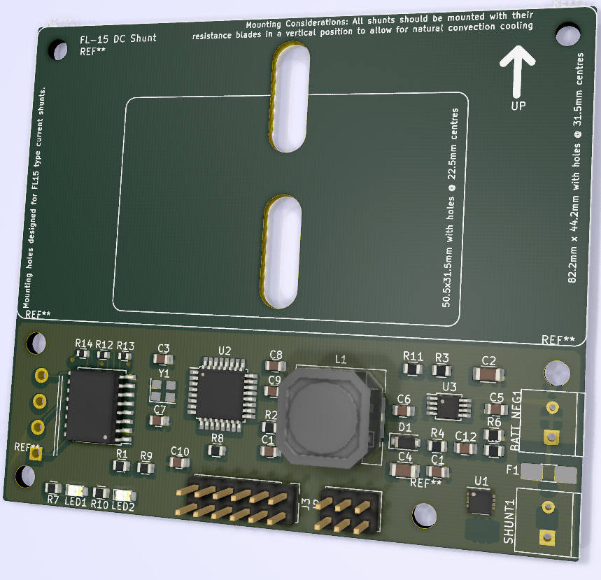
At the present time, my thoughts are still to build a standalone current shunt, with isolation, voltage and current monitoring, hopefully SOC calculations and an industry standard comms format.
Whilst I appreciate this won’t fulfill everyones design goals, I still think its the best way forward for a DIY product.
I expect this will also need a new controller circuit board. I’ll look into purchasing some stock for the forum to save people having to order 5+ when they only need 1.
Good idea. Maybe it would be even better if there could be several people who have boards “for sale” in different regions (EU, USA, RU, etc.). For me. for example, it would not be a problem to have some boards “in stock” ready for delivery within Germany.
I was going to use this for current monitoring (ACS758LCB-100B-PFF-T) 100A bidirectional, feed it into a 24 bit ADC onto I2C bus & away you go, the spare ADC input can be used to monitor the pack voltage via a voltage divider, already bought some from EBAY (link below).
I am going to flatten some copper tube & notch it to slide over the board & solder to the chip tabs, then holes to bolt the cable to. Might even print a case for it all.
@stuart Having a think about this, and been playing around with my current setup, i was wondering if this was possible. An esp32 would allow so much in the way of expansion such as screens, and even more connectivity. My guess is that it could make the web page a bit more snappy.
Back to the usage of our original controller boards, could you still implement a simpler current measurement for those who do not want/need SOC measurements, but want to see instantaneous current being drawn. This would be a slightly cheaper route to take over the full blown SOC shunt that you foresee.
What do you think of my idea of esp32 main controller and esp8266 expansion boards utilizing what we have? Is it a possibility?
Could there be a way to ‘plug into’ the original controller board? Reprogramming the ESP is not a big deal. If there were a new shunt board that would utilize existing controller board connections it would make installation quite simple.
I agree with Fred having it connect to the current controller would be great, Or creating a new controller with the chip on that controller which would allow for more functionality, we are then left 2 controller 1 for those you just want the modules setup and a controller with an integrated gas chip,
I have used shunts in the past where 3 wires are run from the shut to a small head unit, these runs have been anything from 1m to 3m and has worked successful,
Doing it this way will allow different type of shunts to be used and we just set the resistance of the shut in the dashboard
But I am sure that Stuart and the others will be working to a solution which best works for us
I also started to go down that route which is why the ADC connection is on the existing controller, however I didn’t want to expose the 48v (or higher) DC voltages and high currents so close to the main controller board. i2c comms isn’t great in noisy environments.