My understanding is that Low Side is where the shunt goes between the battery negative and the ground rail, whereas High Side goes between the battery positive and the power rail.
The LTC2944 is designed for High Side monitoring.
I think High Side monitoring is generally considered better because Low Side creates a slight potential difference between the battery negative and ground that some equipment/devices don’t like.
I’ve also been working on a gas gauge/trip board design using the LTC2944:
I strapped a bought-in buck converter to it so that I can run as a standalone board directly off the 48V batteries. I added the suppression components as recommended in the data sheet, so hopefully I won’t suffer and noise problems.
The idea is that it would be placed close to the battery and sit there monitoring and figuring out the SOC.
It has MAX485 (or optionally RS232), that I will use for control/query via MODBUS protocol. There is no isolation as I didn’t think I would need that since it’s all referenced to the same ground. Hopefully that won’t prove to be a bad choice.
I went with an on-board ATMega328PB since that’s what I had in stock. I also added a big-ish FET that should be up to firing the solenoid in my shunt trip, plus a couple of other opto-isolated outputs for currently undetermined future use.
Soldering the 2944 chip was actually surprisingly easy. I used a heat gun though. I think it would be much harder with a soldering iron.
You can just about make out the chip here (IC2):
Really nice design, and fun to see, that you decided to go with the same design as Stuart and George decided.
Leaving out RS485 isolation (Or similar) can cause a lot of melted insolation from the wires if somebody by purpose or not decides to power the controller from one of the batteries (Except from the battery closest to gnd)
Adding isolation also means, that you in the future, if Stuart decides so, can change the interface for the battery modules without changing controller and shunt-circuit
Really nice work there @ebsol (Cliff) how easy was the 2944 to program for ?
The isolation isn’t a problem if you know what you are doing (and it looks like you do!) and have a controlled environment - if everything is running from the battery negative all good.
Unfortunately we can’t guarantee that in the DIY world, people have strung all sorts of things together (good and bad!) and a battery with 20 or 30 kWH of storage in it has a whole lot of potential to make things go bad really quickly
I try to keep my connections well labelled to take the guess work out of it while connecting things up. Otherwise it’s too easy to assume or just guess rather than go and look it up to be sure.
I’ve only just finished assembling it so haven’t got into the programming yet, although I made a prototype about 6-month ago and I remember it being pretty easy to pull out the voltage, current, temperature and accumulated charge.
The hard part will be working out and tracking the state of charge over time.
I don’t intend to fully charge or discharge the cells too often (which is required to calibate the SOC), but try to stay within 20%-80%.
Factor in the cells ageing or me adding/removing cells, there’s a lot to keep track of.
The chip does not do that itself, it’s just a coulomb counter.
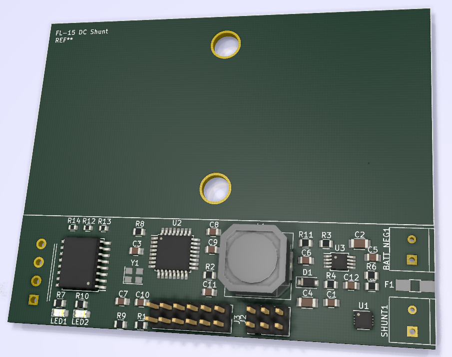
Heres what a potential PCB could look like. Using the FL-15 shunt dimensions from here the PCB could be screwed/bolted to the shunt for mechanical stability. The board is 82.5mm wide and 66.5mm high
I’ve exposed the spare ATMEGA pins in the 12 way header - not expecting to need these, but doesn’t cost anything to provide them.
@stuart
You guys are amazing. Do you have this hobby as full time job
It’s your design and I’m very impressed with this diyBMS project, so please do not consider my inputs as criticism
I don’t understand why you want the 2 shunt connection holes in this direction
why not have the electronics parallel with the shunt, and cut away PCB to the left and right of the holes, so you have room for some beefy cable shoes ?
They are not shunt connection holes - just bolt holes - the PCB would sit underneath the external shunt. It should align with the 5.5mm holes. You would still need cables from the shunt bolts to the shunt1 connection on the board.
@stuart
Looks good.
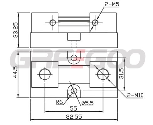
A suggestion:: Although the FL-15 is a ‘standard’ there are differences between the mounting footprints… Watch the edge of the shunt housing and the circuit. The attached is a Chinese supplier extract.
I thought the high side shunt was beneficial to accumulate the power. At every instance you’re sampling the amps, and you’ve got the volts to determine the power. I was thinking that high side was better for that reason, but state of charge is about the amps, right? If I think about it, do I really care about the power?
I don’t see why any equipment could know anything about the “true” battery negative. There should not be anything connected to that post except the wire going to the shunt, and the wire going to that cell’s diybms module. The 2nd cell’s negative is not bothering any other equipment so why should the first cell’s negative bother anything?
How is the shunt any different than one more cell? Why is the 0th or nth DIYBMS module any different than the shunt measuring circuit with respect to isolation and physical placement relative to the controller? Isn’t a DIYBMS cell module pretty damn close to being the shunt power board? The shunt is providing only 50mV max, so you’d have to sort out it’s 3.3 power source. Then write some code for the ATTINY and voila! I don’t know anything about the module daisy chain communication protocol, so I have no clue if it would be trivial to throw in this amps number in the stream of info.
The controller is powered by a USB cord, right? So it has ground from the business end of the shunt, not the battery side. So, the controller and all equipment has the one ground.
If you go with low side, then I think there are lot of other choices. The ltc2944 was the only choice to get over over 48v.
Why do this? There are so many different shunts out there. I’ve seen photos of people’s DIY batteries and they frequently have the shunt bolted to the battery negative.
I think the architecture you created with the n modules makes your BMS unique in it’s flexibility to handle any pack voltage, and any size batteries. Your bolt holes seem to violate that design goal.
Why do you care about the “true” SOC? All you really care about is the usable SOC, right? So every time the controller clicks off the loads, or clicks off the chargers, it will also re-calibrate the capacity.
If there is any merit to the idea of the ATTINY being the counter for the shunt/amp accumulator, then the algorithm would be open source and we could improve it over time. I mean why would the ltc2944 do a better job than open code in the ATTINY?
Why not make the shunt reader board and the module board identical? This would simplify ordering on jlcpcb. Use the ATTINY to sum the volts differential over time and accumulate the SOC info.
Add another Jst connector for power. With a software switch, or a jumper, or maybe if the measured volts is < 50mV automatically behave as the shunt reader board.
Have these communicate with the controller via the same daisy chain.
The power resistors would be unused on the instance that is a shunt reader, and the power connector would be unused on the cell balancer instances.
I can plug one in for my battery shunt, and another for my solar shunt. Others can add one for their inverter shunt if they feel like measuring their separate loads. If the
Regardless of how it is measured, you want the shunts with as short a wire as possible to the battery, and thus the shunts will be as close to the cells and the controller as the balancer modules. And thus they have the same physical and electrical isolation requirements that a cell module has.
I did mention it was a prototype, seeing if it’s the right way to go, you don’t have to use the bolt holes and as there are so many different shunt sizes it probably doesn’t make sense. But anything which helps physical mounting of the pcb is good in my book.
The controller ground is connected to whatever is on the end of the usb port.
However all the modules are using their own virtual ground, all at different voltages. If you take a voltage reading from the negative on one module to negative on another module you will get a voltage difference.
Right, this was in response to the posting that was saying that the negative of the battery is at a different voltage than the negative that is used by the equipment, including the controller, when using a low side shunt. I was arguing that that 2 negatives seemed like a poor argument for the benefits of a low side shunt.
My thinking was that a low side shunt was a benefit because the shunt reader is dealing with 50mV above ground and thus there are a lot of counters to consider, where-as the 2944 was the only > 48v that we found.
Do we have any solid reason to believe the accuracy is needed? When I started thinking about this a week or so ago, I would agree. But now I’ve changed my mind. At least in my use case, the SOC counter will be reset almost every day because I have solar. I couldn’t care less if it reads 5% when the loads are shut off, vs .0001%. I am looking for more sun, or shutting off loads, or turning on a charger when I am near 15%.
Even if this is for an E-bike am I going to rely on the SOC to be so good that I’ll take the bike out for a ride when it reads 5% and be disappointed that it shuts off quickly?