What is the theory as to the cause of the voltage drop? My cheapo multi-meter reads 3.2 on the cells the whole time, and 26.x on the pack. The digital reading on the inverter shows the same.
With the experimental module code it works better. I saw the comms fail to get through the modules, several times, but it seemed to recover. After a while it failed and did not recover, even after I removed the load. I had to disconnect the modules from power and reconnect, to get them back.
It seems to be the same module that dies. I moved it from the 5th to the 4th position and now I see 3 green lights before they stop.
Once, I saw the green leds going across the pack, but the 4th module did not light up. The controller reported that module at 4.5v. The digital meter said 3.2v. The red led was not on, so I assume the module did not actually believe it was a 4.5v. It did not recover to normal readings even after I removed the load. I had to reset it to get rational readings again.
The amount of load makes a difference. If I have just my heat gun on, the modules keep talking and reporting reasonable voltages. If I add the water heater (1400 watts), it starts to go bad.
The higher the load, the lower the pack voltage reading via the INA chips. As low as 21v. The two chips read the same (one for PV shunt and one for whole pack shunt, both have the same pack voltage)
multi meter and inverter report 26.x volts regardless of the load.
I not been able to get a reading from any cell less than 3.2v at any time.
With just one INA chip connected to the sensor wires, no difference.
With just one INA chip connected to only Vbus/Gnd, the V reading looks good. When I add in the one shunt sensor wire pair, then it fails.
Modules crap out (one in particular seems to be the weakest link), when the inverter load is high.
The modules still crap out with or without the INA sensor wires connected.
With the heat gun on (medium load), the modules work, but you can see the LEDs stumbing. If I measure the weak link module’s voltage with the multi-meter, that module will fail. This supports the theory that the modules are at the edge of just enough volts.
Modules usually do not recover comms after the load is removed.
I previously overcharged my cells. They are fat, so they certainly won’t perform like new. The heat gun fan speed noticeably sags when I add the water heater load. The A/C voltage is like 80v when both loads are on.
They were overcharged because the controller had just the one rule to shut off charging when a module reported > 3.550v. There was no shut off rule when comms was lost. I believe the modules crapped out from an inverter load, and did not recover. If there was an inverter load, the net charge would have been close to zero and would not have over charged the cells. The loads were off and the modules did not recover reporting.
When I put a 40amp DC load (slide motor) on it, everything reads properly.
Thoughts:
Maybe the voltage is sagging during the sine wave’s rise, and the INA properly reports that, and the modules experience that too. Why doesn’t the digital multi-meter report that too? Does it only report the maximum “average”?
The DC load does not cause a sag in voltage, so maybe the internal resistance of the cells is crap and they cannot keep up with the sine wave demand of the inverter. Except that I am pretty sure the reason they were overcharged is because the modules crapped out. When the cells were healthy, they would have had very low internal resistance. If I am not mistaken, the internal resistance tells us how fast it can deliver the amps, and I assume that means the voltage stays steady.
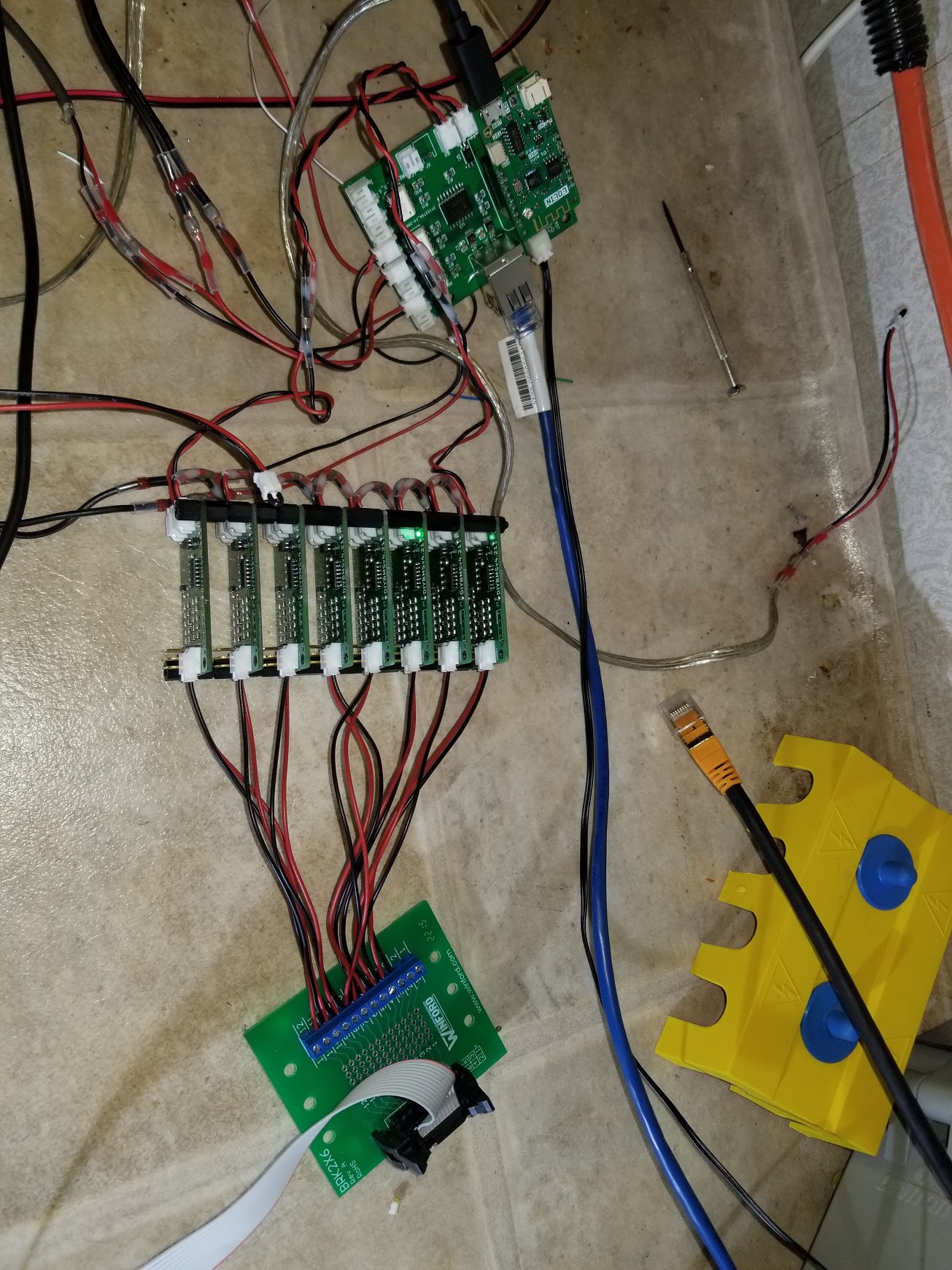
I have a converter board that takes the ribbon cable from the cells and breaks it into the wires to the modules (see photo below). I measure the cell voltage on that blue screw terminal thingy. This means I am measuring the cell voltage with my multi-meter close to the modules, not close to the batteries.
It’s not about the 2x INA but instead the connections from the INA to external devices.
Try connecting only IN+ and IN- and see if you can sense the load via the shunt. Then try connecting IN+ to VBUS since you mentioned you are using high-side sensing.
Also can you opt for the same length on the wires fro both the shunt and battery?
Sorry, I don’t understand. Is “external devices” the chips on the controller board? I called this the “logic side”. I cannot disconnect that since it is a PCB. However, I have 2x INA break out boards that I can wire up to a esp8266.
I have done that and the current looks reasonable.
The normal setup has all 8 wires of the same length and all in the same plastic ethernet cord wrapping.
I reran the 1-INA-connected experiment with same length wires and I still recorded the drop in voltage with the load. Note these 2 pair sense wires are not in the original ethernet cord. They dangle separately. Each is a twisted pair.
The module that was less reliable, is dead. For a while it was passing along the data, but it’s green LED would not light. Then the green would not pass pass by it. I was able to program it again, but it won’t turn on bypass which should happen from the 5v power of the programmer. It does flicker the blue.
Devices not physically on the same PCB. IE: the shunt.
Can you run one more test using IN+, IN- and connect IN+ to VBUS? Analog signals are very sensitive to noise and feedback from other wires so it is quite possible that the wires inside the ethernet cable are somehow interfering with eachother even if they are twisted (though that is supposed to minimize it). You might try the following as the connections of the twisted pairs:
The principle there is that signal induced in one loop - one half turn of twist - is exactly balanced by the opposite signal in the next. This will have little effect if the length of the cable is less than the pitch of the twist (and each pair has a different pitch so as to even out the crosstalk between pairs), because complete cancellation can only happen when there’s a complete one turn of twist.
I suggest putting the analogue signals is separate screened pairs if this indeed the problem - has anyone checked that it is not a ground loop that is the cause of the trouble? If all the “GND” points are not all at exactly the same potential, it will cause problems.
The cell modules are flakey. I turned off the inverter and left the set of 7 running (my 8th died). I came back a day later and the controller could not talk to the cells. The cells were flashing blue, but green was not parading across. The inverter was totally off. They are not doing bypass, since I turn of charging at 3.55 and bypass is set at 4.1.
I’ll try that too, and the different pairings.
But this is pointless if the cells are going to be so flakey.
The modules were flakey before the cells were overcharged. I did not put in a pack over voltage rule, so when the cells disappeared, the controller left the charge on.
There were only three modules at that time. The others had crapped out.
I made new modules, but had to solder the attiny this time. (jlcpcb had them for the first batch.)
I am running the experimental branch as of a few days ago when you suggested I try that.
I just did a quick test with the original controller. It kept in touch with the modules even with the inverter with a large load. I want to apologize for failing to test that sooner and thus potentially suggest there might be something wrong with @stuart stuff.
Unfortunately, I did not keep the PCB design. I fixed a connector and updated it, so I have no clue what the layout was.
The INA chips had a .1microf (100nf) capacitor between V and Gnd in their reference circuit. I knew I could not judge what that meant, so I just mindlessly threw it on there for each chip. I assume these are to filter out noise, but without any clue what the resistance might be, I have no clue how to judge the time constant and compare to the 2.4k baud rate. Is there any reason to be thinking these capacitors are an issue?
Other than that, I see nothing but my PCB layout as the culprit, especially with respect to the RX lines and ground in general. Sadly, I have no instinct for this stuff.
Unfortunately, there’s only one cure for that, which is to read all the application notes and study the thinking to get a feel for it.
What can happen - I don’t have your PCB to hand and I’m afraid I’m too busy with other OEM work to take time out to look - is a PCB track is a resistor. You must make sure that this resistance doesn’t cause problems, or that you allow for it in your design. What I suggest you look at is the current that’s flowing in all the tracks that should be at the same voltage. If there’s significant current - and it can be very short duration spikes of current - and the track isn’t thick enough, you’ll get a voltage appearing that has the effect of adding to or subtracting from the voltage you’re expecting at any particular point, and so interfering. A ground plane, where you have a large area of copper allowing the current to spread out, is a good way of reducing that problem as far as grounds is concerned. You might have a similar problem with the power rail too, where the current drawn by one part affects the voltage that other parts see.
Now if you have multiple ground connections between modules, you’re extending that problem significantly, and the resistance of the connection - wire size and contact resistance of the connectors - can become significant.
If you provide a link to that document, I can take a look and try to explain it.
It took me a moment to realise what “microf” meant. Units named after people (Michael Faraday in this case) always have a capital letter: µF or nF. I’ve quoted the rule a few times on this forum. Here it is again for everyone’s reference:
Units & Symbols
The rules are very simple, and in this order of precedence:
Units named after people have an UPPER CASE letter (Ampere, Gauss, Newton, Hertz, Kelvin, Faraday, Celsius, Joule, Volta, Watt, etc.)
Multipliers greater than one have an UPPER CASE letter. (Mega, Giga, but tera and kilo are beaten by rule 1 - K for absolute temperature after Lord Kelvin, T for magnetic flux density after Nicola Tesla.)
Units not named after people, and multipliers less than one, have a lower case letter. (metre, second, gram, milli, micro(µ), nano, pico.)
So two very common errors: Mhz is always wrong by rule 1, mhz is always wrong by rule 1 and most probably wrong by rule 2.
Some commonly confused are: Siemens & second, Kelvin & kilo, Newton & nano, Tesla & tera.
@John_Taves You’ve just sparked a thought here. As you’ve highlighted your controller PCB is different to the original.
Most likely the connection of GND to the shunt is also potentially introducing noise onto the same GND line that is uses for comms between the cell boards, which only use TTL level signals, which don’t do well in electrically noisy situations.
I think the best solution if i2c is going to be used more generally than for just driving relays, then going down an electrically isolated i2c route may be a good move ?
Sorry, I didn’t spend the time to figure out how to type “µ”. I still don’t know how to. I copy/pasted from yours. Yes, I should have used upper F too.
Not sure what you mean here. I connected the modules correctly. RX->TX and each is powered by an individual cell. They are all nicely isolated with the EL3H7.
The modules are lost when I run the inverter with a load with the shunt wires connected or disconnected. I have not tested to see if they keep communicating without the shunt and without the inverter. Without the inverter running with a load, they seem to communicate for long stretches of time so it is difficult to know what affect the INA/shunt wires are having.
My thinking is that I should focus on getting my controller to work with the inverter loaded and ignore the INA/shunts for now since that failure is trivial to repeat.
I used easyeda.com to make the circuit and put that into a PCB. I used the auto router and stuck to the default trace width (.26mm). I made 2 ground planes, but did nothing more after the auto router did its thing.
I am redoing the circuit:
to have a DC/DC chip SCWN06B-03 to provide the 3.3v. This will mean that I am going to put a big Gnd lead onto the board along with the 24v power to that chip. Right now it has gnd from the shunts and from the USB. (I did try to connect a decent wire from ground to the board, but it had no effect on the modules crapping out.)
I will review all the routes and simplify and shorten them where they are doing higher frequency (i2c and serial) at the expense of the relay stuff that is near zero frequency.
I will fatten the Vcc trace (.4mm) and connect as many back to Vcc as possible. Essentially it is a long route that ends at the farthest chip. I will not only shorten that, but also add more traces directly to the chips.
I will throw a bunch of vias to connect the ground planes in areas that are more remote and to fill in islands.
Good idea, thanks. My software is reading the INA chips 2x per second. I will do an experiment where I turn that off completely and see if that affects things.
If I discover that the i2c is an issue, maybe I should put the INA chips onto the module serial daisy chain? My board will have the INA’s on it, but it would be no different than a separate board put in series with the cell modules.
Here’s how to get the Greel letter Mu, and a few others:
µ Greek letter Mu i.e. µ (micro unit prefix) Ω upper case Omega, the symbol for resistance. Ω ° degree symbol. ° ± plus-or-minus symbol. ±
Yes, you did the right thing having that - and it would have been a moderately serious mistake to omit it. It’s there - the clue is in the name “Bypass” - to smooth out switching pulses of current that the device itself generates; the pulses are bypassed to ground. On page 30 is a diagram showing the ideal physical location for it.
On my Ubuntu Linux, it’s [alt gr] m, [alt gr][shift] q gives me Ω, and here in Discourse + - gives me ±, [alt gr][shift] 0 gives me °
The ones Bill’s given are all “HTML Entities” and will work on any web page. If you can work out what they are on your keyboard, those work in any text or document.