DIYBMS v4 Shunt Design and discussion

Here’s my options:

  1. Get an oscilloscope so I can see what’s going on. I find used ones, like the ones I used 30 years ago, via craigslist for $150. Or new ones from $50 up to $500.

OR

  1. I found a circuit that uses the INA226 to measure -48v and is isolated from the microprocessor. It seems pretty easy to copy that circuit for my purposes. The INAs are powered from the battery using a zener diode and voltage divider resistor. Also, I noticed that when my laptop is powering the wemos from battery (not connected to ground), the modules keep communicating even with a large inverter load. So, I will also add in a meanwell (SCWN03) isolated power supply to the board. This will solve another problem where the wemos clones don’t seem to have enough power compared to the Lolin, but my Lolin has a flakey usb connector.

I am a software developer, and whenever something does not function properly I figure out why. Or rather, the software always functions as programmed, it is just a question of correcting my confusion as to what I actually programmed. In this electrical circuit problem, I feel like I am finding circumstantial evidence, but not proof. It seems like if I do #2, I am doing a better job of attempting to follow best practices, but ultimately not really understanding what the circuit was doing. If I attempt #1, I might get a lousy scope and fail to find anything, or might get a good scope and find some crap signals, but end up with no clue how to fix them other than do #2. Thus wasting the whole effort and learning nothing.

The problem with #2, is that the basic controller with the cheap usb power works just fine with the modules, but my controller with no shunt stuff connected and the i2c polling of the INAs turned off, cannot maintain communication with the modules, which tells me that my pcb design was bogus. Although, maybe with a scope, I could spot that the basic controller struggles with the noise from the cheap-o buck converter.

Much thanks for any advice you all might have.

jt

I’ve been watching this thread largely from a moderation viewpoint rather than involvement, and I can see you’ve got a serious problem and you’re getting frustrated. If you’d like me to take a look at what you’re doing, I need a link to your present hardware design (or better, post the files here). I can’t promise when that might be though, because I’m already heavily committed.

If you’ve got an intermittent fault, which it does look like, you might never find proof. All you can sometimes do is change things that ought to make an improvement and see if the problem goes away.

Sorry, I did not intend to convey that. I do have a serious problem, but it’s trivial to solve by purchasing a battrium or electrodacus BMS. I wanted to learn this stuff. So far, I think I’ve learned a ton of stuff. I’m having fun and blowing a bunch of money that makes this completely unjustifiable.

I did not keep the design files for the one that is alive and failing. Thanks for offering to look at it.

That’s what I concluded. I think the fundamental problem was the lack of isolation.

I went ahead and made a new design that isolates the DC/DC power and the INA chips. I have to say a big thanks to you, @Robert.Wall, because your offer caused me to export the schematic and somehow I spotted a stupid error. I had the i2c isolation chip backwards. I pretty much had every pin on that thing wrong.

The board will be $70 for 5x from jlcpcb. It only requires through hole stuff to be hand soldered. It has 6x relays, 2x INAs to measure current from the pack and the PV array, and it takes a thermistor for pack temp. The INAs are isolated and get their power from the pack using a zener diode at 4.7v to supply the INA Vs.

Schematic and PCB are attached. If someone was willing to take a look and render an opinion I would be very grateful. I did not know how to export the PCB such that someone could review it easily. I made all this on EasyEDA, and I think it is trivial to share out those files for others to log in and view them. I have to say that EasyEDA thing is awfully good.

Schematic_Isolated_2020-09-13_20-36-37.pdf(108.5 KB)
PCB_ISOPCB_2020-09-13_20-36-11.pdf (646.7 KB)

Using a voltage divider is okay for measuring voltages, but don’t use it to power a circuit from a higher voltage. The resistors will draw a lot of power (relatively) so drains the battery it is trying to measure!

John, powering the whole INAVcc line from the battery pack with only a diode to drop the voltage is going to cause problems, thats a lot of power to expect the diode to handle 24x7 - its going to get hot.

I’ve not used them yet, but if you are trying to build an isolated circuit take a look at the miniature isolation transformers - search for “B0505S-1W”

It won’t reduce the voltage but will separate two sides of a circuit.

Allied to that - there’s no smoothing on that supply, only the four 0.1 µF decoupling capacitors to take out any noise from the zener.

It looks to me - from the numbers for output ripple and noise - you’ll still need to follow that with a 3.3 V fairly high performance regulator to give a stable supply for the INA226.

I’ve only been able to look at the schematic in any detail, and apart from the isolated power supply (see above), I can’t see anything obvious.

It’s very hard trying to make sense of the PCB layout without the ability to highlight tracks and relate them to the schematic, so there’s not much I can do there until you figure out how to post the complete set of files.

@stuart and @Robert.Wall

Thanks for the feedback!

I have no problem posting, I just don’t know what type of files to provide. Is there some standard file type? I have no idea if easyeda is well known and used.

I made mine easyeda stuff public, so anyone can view it, at: https://easyeda.com/johntaves/isolated and I assume someone can click on the various traces and make sense of it.

The meanwell provides regulated 3.3v. I assume @Robert.Wall is saying that putting the B0505S-1W across the iso barrier so that it takes power from the meanwell just like the rest of the controller, it would still need additional regulation on the output side. If that is true, then maybe I should plop another meanwell on there to power the INA side. The meanwell is large, but whatever.

Again, thanks for the advice

I don’t have EasyEDA, so I’ve never used it. (I’ve only used Eagle - as used by OEM.) I’ll download it and see what might be needed.

Is “meanwell” the same thing as PWR1? If you want to use the existing 3.3 V, you want a 3.3 V → 3.3 V (or 5 V if you need the second regulator) DC-DC converter - there’s every indication that the 5 V - 5 V converter that Stuart mentioned will not work.

You don’t download easyeda. It’s a web app. Just follow the URL. You probably have to create an account on the website though. Attached is the gerber if that helps.Gerber_ISOPCB.zip (180.5 KB)

Yes, the SCWN03 is a regulated DC/DC isolated power supply. 24v → 3.3v

You are saying that the one stuart mentioned will not work because it is not regulated, right? I am clarifying because you are also pointing out the 5V vs 3V difference, which is somewhat obvious.

I am not finding a lot of choices of regulated and isolated DC/DC converters. I find isolated DC/DC, but whenever I try to find “regulated” along with it, I get larger stuff for many watts.

If you feel that they key is to have regulated output, I would just put another Meanwell SCWN03 on there and draw from the 24V. Meanwell has a dual output version, but the dual won’t give me 3.3V.

In that case, I can’t help you - I have a capped data plan from 8 am - midnight, and while I can stay up late to download, I can’t do a night shift for you.

I looked at the data sheet for the B0505S-1W, and on page 2, it says there’s 110 mV p-p max ripple and noise. The INA266 claims a PSRR of 2.5 µV/V for the shunt and 0.5 mV/V for the bus voltage, those values are very good, they tell me that you can expect to see the equivalent of about 0.05 mV due to power supply noise, and if that’s correct, it won’t matter. But even so, I would have doubts about 100 mV or so of noise on a 3.3 V power supply that’s measuring an analogue quantity. Maybe I’m being over-cautious.

The INA266 does recommend a small capacitor across the shunt input (Fig.21) in conjunction with 10 Ω series resistors for filtering. If there’s high frequency noise on the charging supply, then it might be necessary to have those components.

With the zener diode power supply as you have it, then it’s possible that current spikes that the isolator draws will be seen by the INA226, but again according to its specification, they shouldn’t have a great impact. I suggest a capacitor of about 47 µF in parallel with the zener, and see if there’s an improvement, before embarking on a major redesign and new PCB.

What is the actual range of your ‘Vpack’?

8x LiFePo4 cells, so normally 22.4V to 28.4V

I agree with @stuart that the power through the resistor is not cool, roughly 400mW. I think the zener idea is dead.

This new design with the isolated INAs and the meanwell supplying power to the wemos has not been built yet. I have not ordered it, so changes are easy.

The one that is alive, and failing, gets power in 3 ways depending on whether I am modifying the software and experimenting. From my laptop either from 1) battery alone or 2) with the AC cord connected via the inverter and thus grounded to the batteries, or 3) a cheapo USB buck converter grounded to the batteries. This means that for the bulk of my experiments to sort out the causes, I have had a ground loop through the power supply and the shunt measurement lines. And I discovered it does impact the ability of the controller to keep in touch with the modules.

The weak 5v to 3.3v power supply on the wemos clone I am using is also a problem.

So maybe I have been struggling to isolate problems because there are always one too many present.

The INA chips get ground from the batteries and share that with it’s own chip ground, so no matter how religious I get with isolation, the INAs are going to be getting ground through the shunt measurement wires. From all I have read, 3 i2c devices is just not a problem over the very short distances I am doing, so maybe isolating the INAs from the controller is overkill.

I saw that many times and kept ignoring it. I will add the capacitor and resistors to my the existing wiring and see how that affects things. Also I’ll get a Meanwell power supply and wire that up.

I’ve only been able to look at that part in detail, and with the INA266’s and that side of the isolator powered from the battery pack, a ground there should not have any effect whatever. So I think it’s more likely that your problem is with the Wemos side of that isolation barrier. You’ve got an opto-isolator on the Tx line out of the Wemos, why not one on the Rx line? - if the SCWN03’s COM isn’t isolated from the input GND, or PwrGnd is the same as GND, then you’ve got the possibility of a current in one or more of those connections causing an unwanted voltage to pup up somewhere, which is going to cause problems.

The opto-isolation of the TX is in-line with the ‘standard’ DIYBMS controller which is proven to work well with the remote cell modules. I don’t see any reason to move away from this myself.

Are you saying there that there is isolation, but it’s not on the drawing? If that’s so, there’s no way I could have known that.

To provide some background I guess, the master controller (under discussion here) talks to slave modules in a ‘serial’ loop, each slave module is of the same design with TX opto isolated and RX as in the circuit diagram. These slave modules are powered directly from individual cells within the battery.

If I get chance I’ll put together a high level block diagram (unless @stuart) has already got one to hand.

The one that is alive right now, and failing, has no isolation. The circuit you’ve been reviewing is the proposed fix.

That is correct. The module that connects to RX/TX has the same isolation. It’s TX is isolated.

Attached, is what is alive right now.
Schematic_Controller-old_2020-09-15_08-37-48.pdf (91.1 KB)
I am concluding that the fix is to isolate the power and also put the capacitors and resistors on the INA IN± pairs. I am concluding there is no point in isolating the INAs from the wemos as long as the wemos has no path to ground.
Untitled

Wauw…
I did not follow up of DIYBMS for a while, to busy building my Perfect Powerwall :slight_smile:
(One of the things is bus-bars, often highly underrated part of the build. Tin plating when you are new to the whole plating stuff isn’t that easy but nesececery step to prevent galvanic corrosion with aluminium terminals of 280Ah cells)

@stuart, I think your DIYBMS have evolved far beyond people reusing laptop cells to make cheap “Powerwall”.
With current pricing of LiFePO4, being cheaper than lead acid, it’s more and more available.
Take me for example. I have [email protected], 52 kWh Powerwall, max charge/discharge 250-300A

The cells costs about 5000-6000 USD include transport to Thailand.
(At my start in February the price was higher, if I buy today it’s under $5k)

And after 3 different expensive China BMS failing on me, I’ve decided to put my thrust in the DIYBMS community, lead by you, Stuart.
Amazing well I must add.

Yes, I could have bought electrodamus, and if he would have 48/51.2v I might have.
Double 24v is not a real solution but workaround.

The Batrium at + 800 USD… way to expensive!! (If there are valid alternatives)
Especially as it doesn’t do much more then the DIYBMS… (or any other BMS for that matter)

I totally understand the decision to not make it available for sales or free share. (Perhaps not agree)

If you don’t know what you are doing, do not play with this type of stuff!!!
It can/will burn your house down. And probably the insurance will say it was user error, own fault, about the same as arson.

Probably why the Batrium is 800usd, to deal with all the possible lawsuits :slight_smile:

Being member of the forum of Will Prouse, I do see high potential for DIYBMS.

Like @John_Taves stated a few hundred posts earlier, many potential users are scared away with the need to solder and program IC’s…
(What is so easy following your guidelines, a monkey (=me) could do it)
JLCPCB does 99% of the soldering, if they have all the parts in stock.

For years I’ve looked at the people who program adruino as wizards… as it looks magical.

Writing complex software is different story, the programming part is easy, but…
For many people an issue!!

While I totally understand why you don’t want to sell/give away as (almost) turn key solution, programming attiny or soldering skills have no influence on the skills of building a Powerwall.

It’s double.
When I wrote about missing a few cell modules, you advise to ask in the group if someone could spare a few.
While great thanks (no sarcasm) for the suggestion, all the people honor the license, and no one was willing to break it and send me a few for free or cost or pay.
You get my dubio?

If a friend would ask for my help in building them and use for his Powerwall, I would break agreement to do so.

I truly love the DIYBMS for its

  • modular setup.
  • per cell module, each capable of balance “high” wattage (important feature. While it should not need to burn off 850mA, if it does need to burn off additional, it’s great peace of mind to know that it will be well equipped to to the job, not like Daly with 35mA for the whole pack)
  • WiFi
  • easy setup
  • flexibility
  • temperature rules

@John_Taves
I really like your input and improvements.
Am I wrong or did you add ethernet option?
IMG_20200916_120957
That would be great addition!!
As WiFi isn’t always that stable. (Compared to cable)

I do use the Temperature measure of the DIYBMS.

Looking at your setup, you decided to take the DIYBMS cell monitor modules away from the cells.

IMG_20200916_121325

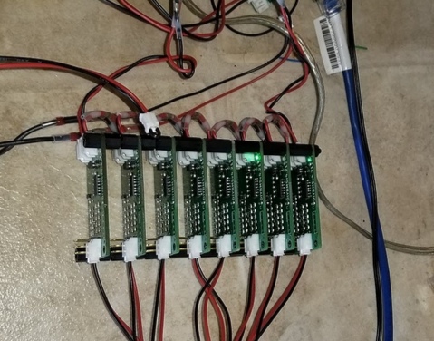
That’s a way of looking at it that I never did!
I understand the ease of access, and extending cables won’t really hurt it’s cell voltage reporting.
It does loose the cell temperature measurement.
Totall underestimated part of BMS!

I don’t talk about freezing point, I talk about cell health.
More or less like humans, same nice temperature range.
They are comfortable at the same temperature, perhaps better with little higher (+45) and less with lower (freezing)
Still they should not get too far above 45, 50-60 is stretching it, and the cells need to be cooled.
Henceforth the importance of temperature measure and the ability to act on it.
Not just an aquarium temperature sensor :slight_smile:

MyPowerwall have 80 cells.
(Yes, if I bought now it would be 64* 280Ah, but I have 32* 280Ah and 48* 152Ah)
The temperature inside this (almost) massive block of LiFePO4 can/will rise at higher (+100A) loads to a range active cooling is needed.

Temperature difference will give different readings on the cells, that is crucial.
Or so my understanding.

I love the work you do and the leaning path you are on.
Stubborn like me and hard to get of taken route… Unless proven needed.

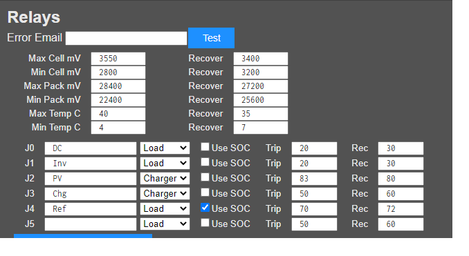
If I understood correctly you stripped out the temperature settings/ rules for relays.

I didn’t install your version yet.
Still in progress of building my Perfect Powerwall.
Something that is supposed to last a decade or longer without any issues, you don’t build in 10 minutes.
Better take 10 days or in my case 6 months :slight_smile:
(Learning curve)

John,
Please let me know if the temperature sensors are still usable for the relays in your software version.

Please let me know if you have added option for UTP cable, and how to get that version of controller board.
(Or perhaps it’s a new Stuart version, that I need to read up about)

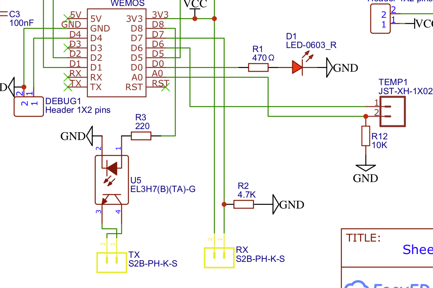
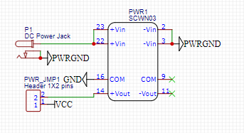
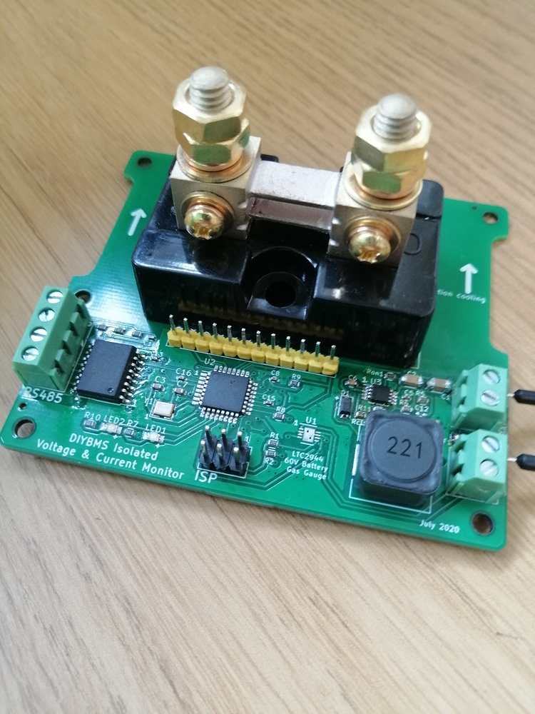
@stuart, what’s the status on the Shunt??
10 August you shown this great progress


That’s a 150 posts or a month ago :slight_smile:
Really like to know how it’s progressing!

It can be I missed a few post’s, as far as I could see, that’s the last progress about it

Keep in mind I rewrote the rules. See below. The idea is that the software shuts off loads or chargers when the parameters are exceeded, where of course chargers are shut off on high voltages, and high or low temps. The loads are shut off on low voltages and high temps. Notice that with the recover values, there is a state for each. For example, the cell mV might be below 3550, but charging is still off because at least one cell is still above 3400. The stock controller code has no recover values and thus no states like that.

Notice too, I removed the time of day rules.

It is trivial for me to add back in the individual temp sensors into the code. Speak up if you want to try this code and I will do it.

No, that’s an ethernet cable used to bring the 2 sets of shunt wires to my controller for current and pack voltage measurements so I can determine the state of charge. When my code loses communication with the modules, it will shut things off if it does not know the state of charge. If it does know the state of charge, it will shut loads or chargers off if the state of charge is below or above its trip value. The main purpose of that is so I keep the loads on, thus keeping the wifi on, so I can see the controller to figure out what’s going on.

Additionally, I modified the controller so that if it does lose connection with the wifi, it will revert to AP mode, so you can find it from your phone at 192.168.4.1 after connecting to the DIYBMS AP.

Unfortunately the INA226 chips I use won’t measure your 51v. However, with low side shunts, you can still measure the amps and get a state of charge. There is a TI example design where they measure -48V and use a trivial voltage divider circuit. Once I solve my problems that could be an option for you.

I don’t know how close @Stuart is to finishing his shunt stuff. My software should be easy enough to support both my INA chips and whatever that new data source is for the current, depending on which is present.

That is more of a product of the fact that my cells are bolted into a space where I cannot get to the terminals and I used the electrodacus so I had a ribbon cable from the cells. I just plugged the modules into that ribbon cable. I will be pulling the batteries out and redoing that mount. I will probably mount the modules as you see, but vertically and next to the batteries.

Regarding temperatures, I felt that since my 8 cells are bolted together, it was highly unlikely that I could measure any cell temperature differences. Taping a thermister to the top or side of a cell doesn’t seem all that useful. Maybe if I sandwich them between each cell it would be useful. In short, I felt like I just needed the whole pack temp, so I added a temp sense to the controller (black wire next to the ethernet cord).
Untitled1

2 Likes

Could somebody explain the importance of a shunt for a BMS ? I understand that it can measure SOC but is that information only for information purposes or is it used for securing the battery?