DIYBMS v4 Shunt Design and discussion

Thanks for sharing the code @John_Taves it will be useful for others to use/modify.

The rules/relays section of the existing code is a bit complex, and I also think it needs clarification and code simplification so it can be isolated and unit tested.

I also noticed that you default to WIFI AP if the router fails. I decided against that as I also look at things from a security/attack (habit picked up from work!) and having systems “fail open” can be a bad thing.

I’ve implemented something similar in a couple of my projects and the solution I opted for is a secured SoftAP rather than an open SoftAP. Adding a password by default for the SoftAP is better than having none in this case (even if the password is the same as the SSID).

Perhaps true, but I’d rather not test it and find out that it is not true. Safety is always the most important concern.

That is good! I’d suggest also moving it away/outside the house into a dedicated enclosure as an added “just in case” measure.

1 Like

I think @John_Taves may struggle with that - think the install is in an RV !

Yeah, that would make it a real challenge. All the more reason to use one of the safer chemistry batteries and to have as much monitoring as possible in place to try and prevent the worst outcomes.

I am getting bad voltage readings from the INA226 when the inverter is loaded. The readings always go low by many volts, instead of 26.5 it will read as low as 22. When the inverter is idling, it is accurate. Of course, a digital multi-meter shows 26.5 regardless of the inverter load.

Also, when I put a load on the inverter, the controller loses contact with the modules, but only if the INA cable is attached. If I remove the INA ethernet connector, the modules work fine with a load.

Unfortunately the batteries, inverter, and shunts are all within inches of each other.

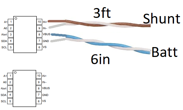
The INA226 has shunt +, shunt -, batt+, and ground that are brought into be measured. Ground is attached to the ground plane of the controller. I am using a high side shunt, so the shunt+ and batt+ are both attached at the same point. I am using an ethernet cable that is less than 1m long to bring the 2 sets (one from the battery shunt and one from the PV shunt) of 4 leads to the controller. The cable has twisted pairs and I am using those pairs properly (1 set of batt±, 1 set for shunt±, repeat for PV)

The controller is powered by a small usb converter, so it should share ground with the battery via that route in addition to the grounds from the ethernet cable.

Unfortunately I don’t have an oscilloscope.

I tried connecting the batt and ground wires to the INA226 with short wires, and the voltage read correctly with a load. However, to do that, I had to remove the shunt wires, so the INA226 did not have shunt+ and - connected. Curiously, the INAs were reporting huge amps, which doesn’t make much sense to me given that they were floating. When I connect the longer shunt pairs, the bad readings return.

The INA chips have 2 settings for the readings. I can set the conversion time and the averaging. I am guessing that the conversion time is the time it spends reading the analog value before converting it to digital. The averaging is done at the digital level, so it’s pretty straight forward. When I set these to minimal numbers, I can get goofy voltages even with no load on the inverter. I originally assumed I was seeing the sine wave of the inverter, so I bumped these values up and it seemed to be solved, but solved only for low loads.

What is odd to me is that the readings always go low. I would have expected that if there is a sine wave of noise either being added to, or transmitted through, the wires it would be above and below the DC, such that averaging would kill it. It seems to me that the noise is always subtracting and thus averaging in those bogus low readings gives a low average.

I’m no expert on circuits, so any ideas would be very much appreciated.

Attached, is my controller circuit.
Schematic_Controller_2020-09-05_11-45-38.pdf (99.1 KB)

@John_Taves can you put some pictures of the setup on-line, might give some valuable information about what could be causing the problem.

I edited the post above, to say that the modules work fine when I disconnect the INA ethernet cord, and they do recover if given enough time after the load has been removed. The controller works fine the whole time.

I will get photos, but now that the problem is clearly arriving through the INA/Ethernet cord, I feel like more wiring experiments will not be a waste of time.

I have a shielded cat8 e-net cord to try, but my shunts and battery negative are like 6in apart, and thus I lose shielding and twisted pairs for a significant portion of the total length of wire. Plus, the rest of that length moves away from the inverter, so I just don’t have hope that shielding will help.

Is it feasible to split the two INA connections into two RC45 connections so you can isolate the inputs with a GND connection in the twisted pair? IE:
1: GND
2: VIN+
3: GND
4: GND
5: GND
6: VIN-
7: GND
8: VBUS

The idea being to minimize the chance of noise between the two INA chips.

@John_Taves when the modules stop responding, do you still see the green LED sequence between the modules, or does the blue LED come on?

@stuart when the inverter is loaded, and the controller has lost connection with the modules, the green LEDs blink normally for the first 4 modules and stop. The last 4 modules blink their blue LEDs.

I’ve waited many minutes after shutting off the loads and still they have not resumed communication, so it seems they don’t always resume normally.

John, can you try this version of the code in the modules.

https://github.com/stuartpittaway/diyBMSv4Code/tree/ModuleCodeImprovement

It resets the serial port should the watchdog timer kick in, along with several other safety checks for over temperature.

I have a previous version controller that has 2x INA but uses the JST connectors. Using the twisted pairs from an ethernet cable, I put just battery power into the INA, and it read the voltage correctly with a big load. I then added another twisted pair down to the shunt, and now the voltage reading drops to like 24 when the load is added (digital meter says 26.3).

So, I think I am doing what you asked. Only one INA is connected. The battery pair are only about 6" long. The shunt pair is maybe 3ft long. Neither have any shielding.

I assume you are referring to the latest.

I am not able to burn the modules with the release where you made the different module choices in the ini. I’ve tried 2 different attiny programmers (see photo) and neither works. It cannot find the target, so I think the windows driver is good.

I copied the module code into my previous version and commented in
#define DIYBMSMODULEVERSION 421
I also had to add:
#include “defines.h”
to diybms_attiny841.cpp

I programmed the 8 modules and there was no change in behavior. Except this time the first module after the green lights stop was not blinking blue. I am sure I saw 4 blue leds to offset the 4 that were relaying the green prior to the update. It seems interesting that it always seems to die at module #5 so that 4 blink green.

I attempted to figure out if your controller software had changes but gave up. I have too many changes in my version and I don’t know what version you might have changed to find just those changes. If you can tell me what to look for in the controller, or tell me what version to compare to, or give me a diff, I’ll update my controller and give that a try.

The controller code is the same - its just the modules that I was interested in.

The ATTINY841 is bad at regulating its own frequency using its internal clock - this jumps about a lot when the voltage jumps about. This seems to be the root cause of comms issues and why I dropped the baud rate to 2400 bits about a year ago. This seemed to resolve the problem.

So when balancing kicks in, if you get high voltage swings on the power cables to the module I think it gets out of sync with the baud rate/comms.

It is just a guess at the moment though! I’ve noticed some ATTINY are worse than others, which is possibly why it seems to stop at the same point. There is a configuration/calibration process that can be done, but I’ve not read into it.

The code in that experimental branch attempts to reset the serial UART settings should the watchdog timer kick in (normally 8 seconds after comms failure).

It definitely sounds like you are having interference between the two INA in this case. I’d suggest split the connections and send one connection per twisted pair with the second wire being GND. Yes, it will take more wires but you should get a more accurate reading.

I did not notice it was a different branch. I will retry.

Also, we are dealing with 2 different problems. The modules seemed to behave poorly when they were dumping power, but I’ve ignored that problem for now. I figure I will make fatter shorter wires and revisit the issue much later. Balancing is not important at all.

The main issue is that I lose comms when the INA wires are connected and the inverter has a larger load. I figure this is more of a clue as to what is happening. If it did not happen, I could hack the problem away by comparing to the sum of module volts.

Why do you say that? The second INA is not connected, except on the logic side.

Just to be clear, it looks like the diagram (pins 1-6 are wired up on both chips, this is a PCB). Especially with respect to the bare twisted pairs taken from an ethernet cable.

  • With just blue/white it reads V correctly.
  • add in brown/white and V reads low with inverter load.
  • Current measurement is garbage too

I do have an INA226 breakout board so I can wire up test thing.

Untitled

I’ll change the order and see if it follows.

It does follow. The same module craps out regardless of what position it is in.

This could be the result of voltage drop on each of the modules causing comms issues as described above, with the ATTINY serial baud rate going wonky.

Hi Stuart. Do you remember me? guy with arduino pro mini’s? I also have to down uart rate from 9600 to 2400 bps because of wrong comms. In my case I didn’t detect it in my house, only when I installed all stuff in my garden shed. Temperature inside gets up to 40ºC in central hours in summer so some modules have wrong comms with others or with controller ESP8266.

With 2400 I have almost no problem. So yes, probably baud rate at 2400 with external crystal/resonator coud be funny with temperature changes or Vcc changes.