DIYBMS v4 Shunt Design and discussion

My head is spinning. I don’t get why I ignore the 3.3v and instead use 1.5v to determine the resistor that will be connected to 3.3v. This is to achieve the goal of a minimum of 5mA through the LED, right?

I have no problem with the fact that the LED has some resistance, but I assumed it was insignificant with respect to the 560ohm R I used to get 5.9mA from the 3.3.

Thanks for your help on this.

The comment is about SAFETY not battery voltage. The TI datasheet provides SAFETY guidelines for usage of the chip.

It may or may not work correctly for ampage, I don’t know for certain as I’ve never used it in that fashion.

Because the datasheet lists the Vf of the LED as maximum 1.3v. You also do not ignore 3.3v as that is the current source for the LED.

Unfortunately LEDs are picky about the current going through them and require a few extra calculations.

I googled and found that R should be Vi-Vf/If, so your math makes sense now. I have not quite wrapped my head around why.

I totally appreciate the help. I’ve got a lot to learn.

I almost always use an online calculator that you plug in known values and it spits out the others for you.

Always here to help and I think we all have plenty to learn.

Of cause not.
My inverters are Grid-tie with limiter, so I can switch them off on the 220V side with normal 3 phase contractor (1 phase per inverter).
And for battery protection rules (overcharge, cell temperature high, communication fault) I use a huge DC MCCB with remote shunt trip.
So in both cases relays are used only for a control signal.

I was taught (long before Spice1 appeared) how to do it with the curve and graph paper. Knowing the fundamentals means that I can still get a reasonably close answer without the modern tools.

Here’s a graph of LED characteristics, lifted from Light Emitting Diode or the LED Tutorial


On it, I’ve drawn (in thin black lines) the 3.3 V supply voltage ( the vertical line), and the characteristic curve of a 100 Ω resistor, but reversed. That’s justified because the LED and resistor are in series - if the LED isn’t there, the voltage where it was connected is 3.3 V but the current is zero - the end of the sloping line on the V axis, and if the LED is a short circuit, 3.3 mA will flow and the voltage will be zero - the end on the current axis.

The point where the curve for the LED and the “curve” (line) for the resistor cross is the voltage and current when they operate normally - for a red LED it’s about 1.8 V across the LED & 18 mA flowing, for a white one, it’s about 2.7 V and 5 mA.

In practice, you’ll choose a current ( = brightness) to operate the LED at, read off the LED voltage at that current, and then calculate the resistor value. You could of course draw the line and get the resistor value from the slope of it.

100% correct! I prefer using the calculator mostly to save a bit of time in figuring out a ballpark figure for the R and then adjust up/down slightly to fit a convenient SMD component from the available parts list (or what I have on hand).

16s 4 bank setup here as well (fail-safe impossible for charger to overcharge )
just so I can make full use of the 64v max 80amp solar chargers I have
~1kw extra charging capacity than if I was running as 48v banks
tho controllers are only ~$5 to make I guess and then I have more excuses to add more banks :smiley:

edit
and now I have no idea where the comment I was replying to got to … but it had something to do with 4th bank being removed

as for people wanting 8 relays
my plan was to monitor when I have excess solar power
(when battery voltage is 64v)
and dump it into additional
heating / lighting / ventilation for my aquaponics farm all the stuff
I do not want running from grid / using backup battery power for
currently 1/2 of the power the panels are producing is not being used

@John_Taves what is wrong with the tesla packs ?
the 24v 6s74p 444 cell 5kw modules is mostly what I use for 24/48v banks ?

@MasterCATZ if the tesla pack is mistreated, it can burn and nothing can put out the fire.

I made many changes to the controller software:

  1. made it switch to wifi AP mode when it loses connection as a station, so that if one of the relays it controls provides power to the wifi router, I can still see what’s going on on the BMS
  2. removed the rules and in place made a system where each relay is labelled as a load or a charger. Then hard coded logic that monitors the various inputs. The settings screen shot should show what’s happening here. One thing that is not obvious, is that the controller will stop charge or loads if the cells stop reporting and the state of charge is above/below the trip point for that relay. This means that even if the relay is not using the state of charge to turn on/off, the trip value should still be set so that the controller will keep the loads/chargers on when it loses contact with the cells as long as the state of charge is within bounds set by those trip values
  3. I moved the java script that was in default.htm to pagecode.js and a new file charts.js. I did this because I was having a hell of a time getting the wemos to refresh default.htm when I made a change to it. It seemed to crap out, so I figured I would make the file smaller and see if that helped. It did.
  4. I did not bring along the rule code that looked at the time of day or the individual cell temps. I didn’t need either.
  5. The relays can be named, and the status display shows those names. A blank name hides that status.
  6. There are 3 measurements, pack voltage, cell voltage and pack temperature. All have recovery values, which means that there are 6 potential states that are not obvious by looking at the values. These states are displayed. The photo below shows that I am in cell over voltage, which means we tripped because one cell exceeded 3.550v, and at least one is still above the 3.4v recovery, so charging is off. The 6 are cell or pack or temperature and over or under.
  7. It also has logic to deal with the situation where it does not know the pack state of charge, which happens if the controller reboots. I can manually set my state of charge, so if I upload the software and restart, I don’t have to wait for it to reach the max (or min) to know the state of charge.
  8. You can turn off a relay by clicking on the relay status. In that state the controller won’t turn it on. You cannot force a relay on. OK, you can by making bad settings choices, but that’s the point.

I have been testing this for the past 2 days and it has worked well. I have problems with pack voltage measurement, where it reads really low voltage when the inverter has a decent load on it. I think that is just a matter of getting the INA226 chip settings right, but maybe I need to filter the noise electrically. But, the cool thing was that the software shut stuff off properly. I then found the controller properly making an AP wifi and was able to connect and see what was going on.

I also experienced the modules freaking out (see the DIYBMS v4 forum), and during that the controller was behaving like a pro. It did the right things when the modules went bye bye.

If anyone wants this code, speak up.

1 Like

If you can, please do share as I think some of these features you have made may work well for the general usage.

ESPAsyncWebServer has a few limitations, often smaller files work better than larger. I gzip compressed all content served by the web server and found it helps considerably. As for the refresh issue on the default.htm that might be due to a missing cache-control header for the “static” content, I’ve found holding CTRL while clicking the refresh button usually works around that missing cache-control header.

also would be interested in looking at your code, bit of a shame the time / temp rules where not carried over

as I was planing on using them to help fine tune the relay I want running for boosted heating of fish tanks

ie) cold day allow the relay to run batteries down at a slightly lower voltage warm day only run when batteries maximum charge and excess power available

is it possible to do capacity tests with this ? I feel like I have a tesla module on its way out and trying to decide which ones I should break down

I committed my code to johntaves/diybmsv4code.

This code goes with the controller I made that has 6 relays on board, 1 external thermister connector, and 2 INA226 chips for current measurement. However, it works with the base controller. If it fails to find the INA chips, then the settings and status things that need those chips disappear. However, I have not fully tested it with an original board. One of the main reasons for this new code is to take advantage of the current measurement stuff and be able to use state of charge in controlling the relays.

I can commit that hardware design if anyone wants it.

@MasterCATZ, I totally killed the original rules functionality. It seemed like a generic rules processor that could do anything, but it couldn’t. I didn’t figure out a way to keep that do-anything style while supporting the functionality that I felt was necessary. I actually made a version (see screen shots either on this thread or the other thread) that used the original rules method, but added states for hysteresis. It might have handled everything, but I was not really confident. My head kept spinning with respect to applying the rules sequentially. For example, if you put the rule that the load relay be shut off when the battery is less than xV, and of course that is the highest priority rule, then oops it overrides the fish tank rule that was a lower priority and turns on the loads when above xV.

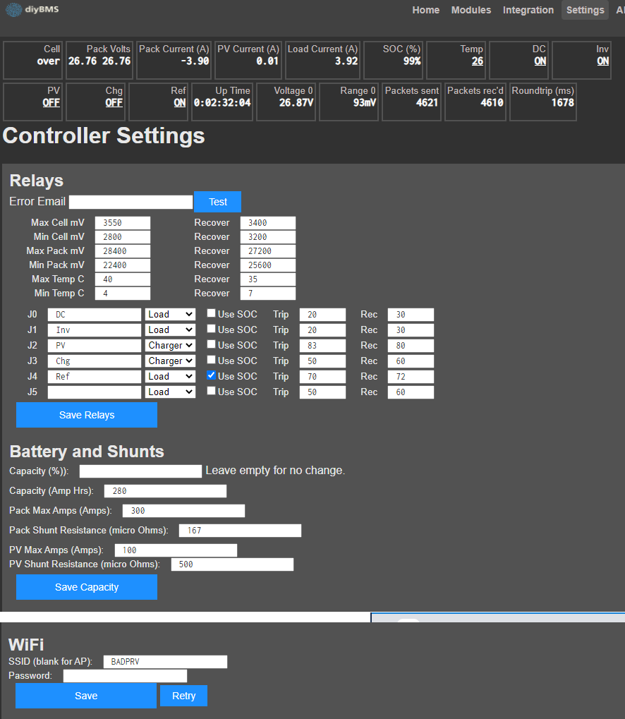
I had to be confident, with straight forward logic, that the loads and chargers would be shut off when the limits were hit. This required a simple UI and simple code. I felt that the rules made my head spin with the assorted states and even if I got the code right, I was not convinced the user would set the rules properly. The basic idea is that you tell it the limits, and which relays are loads and which are chargers, and it will make sure those limits are not exceeded.

I intend to put in an email notification (so you can send an SMS to your phone) if it commands that loads or charges be off, and it still has current going in that direction. This would happen if you lied about the relays, or you’ve shorted them on.

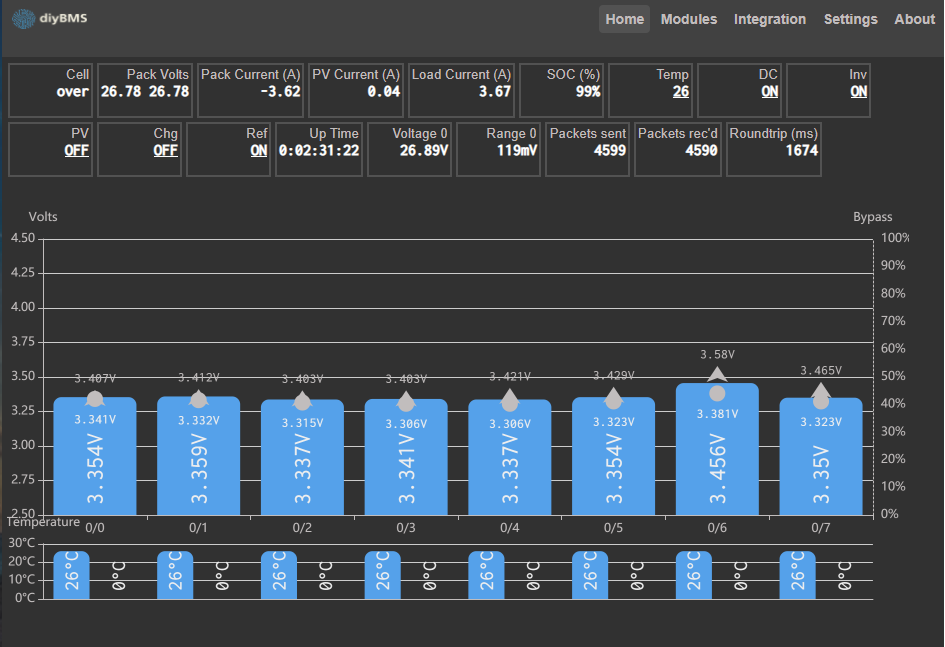
Yes, this will provide the capacity test information. You provide the capacity, and the max cell and min cell voltages, then charge it until the max trips off the chargers. The code then shoots the state of charge to 100%. If it reaches 100% prior to tripping off, it highlights the state of charge display to indicate it’s above your estimated capacity. If it was not at 100% when it tripped off, it displays the milliAmpHour addition it had to do to get it to 100%. In other words, it shows the difference between your estimate capacity and what it counted. The same thing happens at the bottom. So, you’ll charge it up, and thus establish your 100%, then throw on the loads and wait for it to trip off. As long as you’ve over estimated your capacity, it will show the capacity it thought you had before it tripped off.

The individual cell temperatures are not supported, but it will take no time to throw them back in. I didn’t really see the point. I have an external temp sensor on my controller that provides me with the pack/ambient temperature necessary to keep from charging when near freezing.

Regarding the fish tank rule, it will turn on/off based on state of charge. I did not do anything where you can look at temp and state of charge.

what if the CELL ( consisting of several smaller cells connected in parallel) gets too hot during charging ? why don’t You measure it’s temperature ?

Thanks! For those wanting a direct link to the code it can be found here.

The module temperature sensors are used for at least two purposes:

  1. Module temperature while in bypass mode.
  2. Battery temperature during charging.

The module temperature is less critical than the battery temperature which can be used to detect a battery pack that is having issues (ie a heater) but depending on the location of the thermistor it may not be as accurate.

Most likely it would make sense to re-add this functionality back in and have the rule setup as a very simple rule: module internal/external temperature over X trigger relay Y.

The rule engine is rather complex but does generally work. I’m in agreement that it can use a bit of cleanup and perhaps expansion with some sort of dynamic rule creation/evaluation.

Good point. I just have single LiFePo4 cells, and I won’t be getting near .1C current, so I wasn’t concerned about individual cell temps. I doubt I can position a sensor to measure an interesting difference.

But it is no big deal to throw cell temp back in. I’ll add it to my to-do list.

Right now, I cannot remember the situation that the rules could not handle. I needed one rule to be a higher priority than another, but also for a different situation, it had to be lower priority. I need to get back to work, but hopefully I will find the time to write down the scenario that the rules system could not handle.

One thing I am doing is to allow chargers and loads to be on even if the cell monitors have died as long as the state of charge is within bounds. Maybe that combined with 2 different loads… I don’t know.

can LiFePo4 cell get faulty and start to overheat in the future causing risk of fire during charging while You are out of the place ?

My understanding is that LiFePo4 just won’t burn. Even if you short them, they end up a smoking pile of goo, but not a deadly fire. Mine are aluminum cases, so its just not easy to get a fire.

I know from first hand knowledge that if you over charge them, (because I was an idiot and failed to set the max pack voltage cut off, while knowing that something made the cell modules freak out and stop reporting), they expand and vent, but don’t really get hot. They bent some serious steel and are now bloated, but they still work.

They are packed side by side, so they have a lot of relative surface area in common with each other that should conduct heat nicely. Plus they are close to 3"x7"x8" so there’s a lot of mass to surface area in each cell. I am no expert, but I doubt I can position a thermister to do any good.

I suppose I could build my new pack with thermisters sandwiched between the cells. I don’t see the point. That seems like a very low probability of failure, especially compared to all the ways I can muck things up.