I thought @yar_leo listed the reasons on a posting. The TLP222A are just sockets (2 relays per package). They are THT chips. I only want 4, but put 6 on mine.
They can handle any voltage if the shunt is low side. Again, it makes no difference if the user does not want these chips, but a huge fraction of the real market does want them. If jlcpcb will stock the ina229, then you can run 48v into it without hand SMT. They are the same footprint (according to @atanisoft).
I keep running into the same argument. @yar_leo keeps making the simplistic comparison that some might want it and some might not. You are saying the same thing. Yes, maybe your current users are balanced between wanting it and not wanting it. This logic is absurd. You have absolutely no idea how many people have investigated DIYBMS and went elsewhere because they added up the headaches of soldering, buying a relay board, connecting god knows how many wires, and oh, wait! this thing does not measure state of charge?!?
If one thinks about it, the priorities are all backwards. A solar shed, off grid home, RV, will all work just fine without the cell balancing. If I top balance my cells once, they really won’t need any balancing for a long long time. I need 8x voltage measurements going into the controller and I must have state of charge, and I must have relays. The number of people that have looked at DIYBMS and gone elsewhere is probably huge compared to the number that stayed.
Again, putting the INA and relay sockets onto the board does not stop you from making it modular and expandable to support other shunts. It is trivial to ignore those chips.
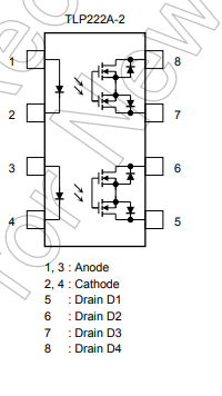
Sorry should have given a bit more context to them. Using a 3.3v supply, 560Ohm R, LED Vf of 1.3 (max from TLP222 datasheet) it results in 3.57mA current through the LED using LED Resistor Calculator. From the TLP222 datasheet it lists 5mA as the minimum recommended current for the LED. To hit the 7.5mA typical/recommended target it would need to be ~266Ohm R. A 240Ohm R yields slightly higher at 8.33mA.
Normally Watts are tracked for thermal dissipation purposes, as an example the TLP222 devices can dissipate up to 400mW per detector and 50mW per LED (there are two LEDs and two detectors in the package I believe).
The PCF8574 can source or sink around 100mA of current with each pin sourcing or sinking 20-25mA max.
I don’t agree with this statement. IF you brought brand new cells then yes, but a lot of the community are using scrap cells and they definitely need balancing - hence the DIY nature of this project.
Oh no, I have no clue what that Vf means. I saw it but couldn’t make sense of it and decided ignoring it was my best option (yes, this is pathetic, but I am a novice and can’t absorb everything at once). How are they getting 1.3v across the LED? Am I being an idiot for assuming the diagram is showing me that there is just an LED between 1 and 2? Is there some sort of voltage divider?
Correct, I’ve no idea who went elsewhere - and neither do you.
What I do know, is that there are plenty of non-DIY solutions (Batrium et al.) which cater for that market.
If you are a “tinkerer” you are likely to look at DIY based solutions (usually to save money vs time/effort) and that market is also likely to be custom building battery packs from recycled scrap cells.
Vf is the forward voltage - V for voltage, subscript f for forward. It’s the voltage that appears across the LED when it is passing a current, i.e. lit. On low voltage supplies like 3.3 V, you most definitely cannot ignore it, because it amounts to a sizeable proportion of the circuit voltage.
Yes, but this is a selection bias. That’s the comments you have attracted. My point is that you have not attracted many others. Any off grid solar home/shed/RV is a custom solution, and no, a huge number don’t want to fiddle with used cells. My point is that you are very close to a solution that would appeal to a hell of a lot more.
@stuart, I am only trying to help. I am happy as a clam with my solution (as long as this Vf thing does not mean my TLP222’s will fry). Your work was a huge help to me and I am very appreciative of not only the actual hardware, but a cool project that allowed me to design a circuit that works.
I have software that I can commit if you want it.
I have a solution for myself, so my comments are totally about how to reduce your work load while making DIYBMS appealing to a much larger audience. If my posting and arguments and questions are more hassle than they are worth, send me a PM telling me to shut up.
If you review the posts at no point have I made the suggestion that I won’t support the INA chips or the TLP relays.
What I have been doing is working out how these can be supported and even modifying my new controller circuit to reintroduce i2c. Likewise also finding out how people are using 8 relays.
What I haven’t heard, is how to make the INA “safe” on the controller board for all users
The solution/product and copyright belongs to me, and as owner of the product I can resell to whoever I wish.
Instead of selling this product I’ve given it away for others to use, spent 3yrs+ in revisions, upgrades and helping people - and probably run up a few hundreds in debt for it.
I’m not going to tell you to shut up - but some of the replies do seem a angry !
As I’ve said all along, I’m happy for advice, suggestions and recommendations. It just has to be safely done, there are a lot of people with absolutely no clue what they are doing wiring up massive battery banks for fun. I have considered pulling the plug on the whole project due to that element.
We’ve already seen at least 3 major fires on the DIY Powerwall Facebook group. I don’t want to be part of that.
I don’t see the issue. I just don’t have enough experience to know whether I am ignorant. The INA226 chips have inputs for gnd, 3.3, and up to 48v all within mm of each other. I make the simple conclusion that if TI makes a chip that puts those voltages within that tiny space, then I’m OK running a trace to a JST connector to grab the pack voltage.
How are you handling this on your shunt board? It too would need up to 48v along with the 3.3v, unless you are demanding low side shunt, right?
INA226 is up to 40V… But your point is valid and requires special routing of the traces on the PCB for safety and accuracy. It doesn’t matter if it is high side or low side reading as far as that is concerned.
As long as you also follow TI’s recommended board layout I don’t see any issues with it either. Having a dedicated shunt device (like @stuart is using) shifts the majority of the current away from the controller PCB (or all?) and leaves only a handful of IO pins needed for reading the data from the device. In my original design I had planned for a set of pin headers (or screw terminals) to connect a dedicated shunt resistor.
Sorry, I am frustrated because I cannot seem to get across the point that I am talking about satisfying a large number of users that have gone elsewhere and doing it with less work on your part. Nobody seems to get that putting INA on the board does not prevent a daughter card or whatever expansion you want to provide. But NOT putting INA on the board demands that a daughter card must be bought.
I would not fault you for choosing to do that, not to mention the enormous time sink that it must be for you.
My thinking is that you should either shut it down, or you should figure out how to let it run as a pure open source thing.
Here’s an example to make an interesting point about liability. I made my own circuit by copying the espcontroller circuit. If I blow up my RV, you should have absolutely no regrets or concern. I made my own circuit. If on the other hand, you provide some sort of swiss army knife of a controller where anyone can buy it from your reseller and plug all sorts of crap into these daughter boards and connectors and blow up their stuff, you have maybe a bit more responsibility on your conscious.
In other words, if you are catering to the crowd that finds used cells, has fun wiring up and soldering a lot of different boards, then make them design their own circuits to do those goofy setups. If you provide a basic board (and obviously I define that as having current measurement and relays), you sort of limit the use cases. I’ve argued for a 4x module and 8x module with controller single board. Those “turn-key” solutions eliminates the possibility of someone putting a Tesla pack on it. Those telsa packs are exactly thing thing you don’t want to support if you are concerned about burning down something.
Notice that this is the first time I have argued that more modularity is less desirable.
Yes, my point is that you can let others distribute, support, and contribute much like RedHat with respect to Linux. I mean, if you say “yes, please make a 24v single board solution and resell them with my copyright on it, and you will handle all support issues!”, you’ll suck others into taking your support work load off you. You seem to be spending time to get an OEM to distribute it, instead of encouraging it to happen.
Why? If I have a 48v pack, I can just run 3.3v into the VBus line on the INA226. It’s power measurement will be bogus, but it does measure amps, right? State of charge is all about amps, right?