hi Stuart, hi guys,
First of all thank you so much for initiating this project. I’ve been reading up and following the DIYBMS for a while now. Very nice project!
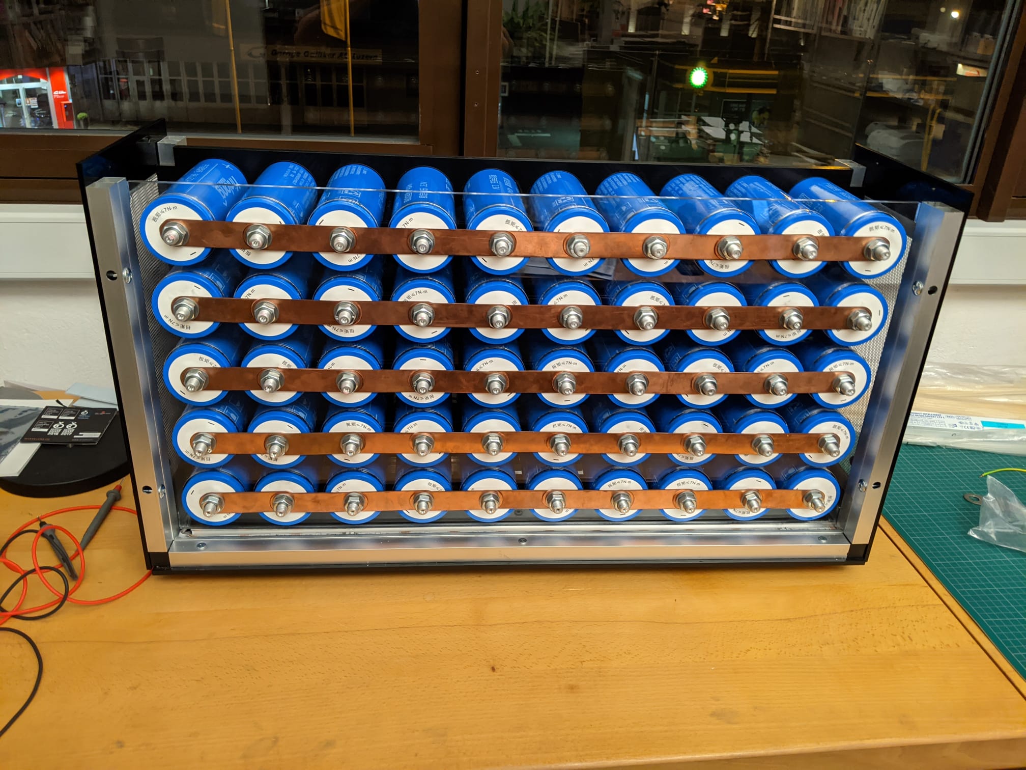
I have an off-grid cabine in the mountains where I am building a solar/hydro fed battery bank out of 40 Ah Lithium titanate battery cells, pretty much similar to what @Ross has built. These cells have 20’000 cycle live time, don’t catch fire and have a wide temperature range, so they are perfect for me.
As is mentioned somewhere here, I’ll have to keep an eye out to not get too low on the voltage because of the microprocessors used (I’ll be operating between 2 and 2.8 Volts). Also, I’ll be using the alternative resistor values on the boards like @Ross 's.
I am absolutely new to PCB design and micro electronics. Now my question: Would it be possible to create a board version with an M8 through hole as a connector (similar to the batrium product)? This would allow for an extremely clean build.
Yes, there is a variant (not created by me) which uses Nissan Leaf cells and connects to them as you describe with a bolt mounting. But I don’t know of one specifically for the Lithium titanate cells - do you have a link to the cells you are using?
The V4.21 boards operate down to around 1.8V (although the V4.00 boards are about 2.2V) so should be okay with the lower voltage. Might also be worth changing the resistors on the LED’s if you are operating at a lower voltage, so they are not too dim.
Are you using multiple cells in parallel? You mention M8 hole, but the cells linked to say M12
I didn’t build it, have a chat with @GeorgeBoudreau, but it works with the controller and the normal DIYBMS code, just a different shape. It uses 8x 33ohm resistors to provide 4.1ohm balance.
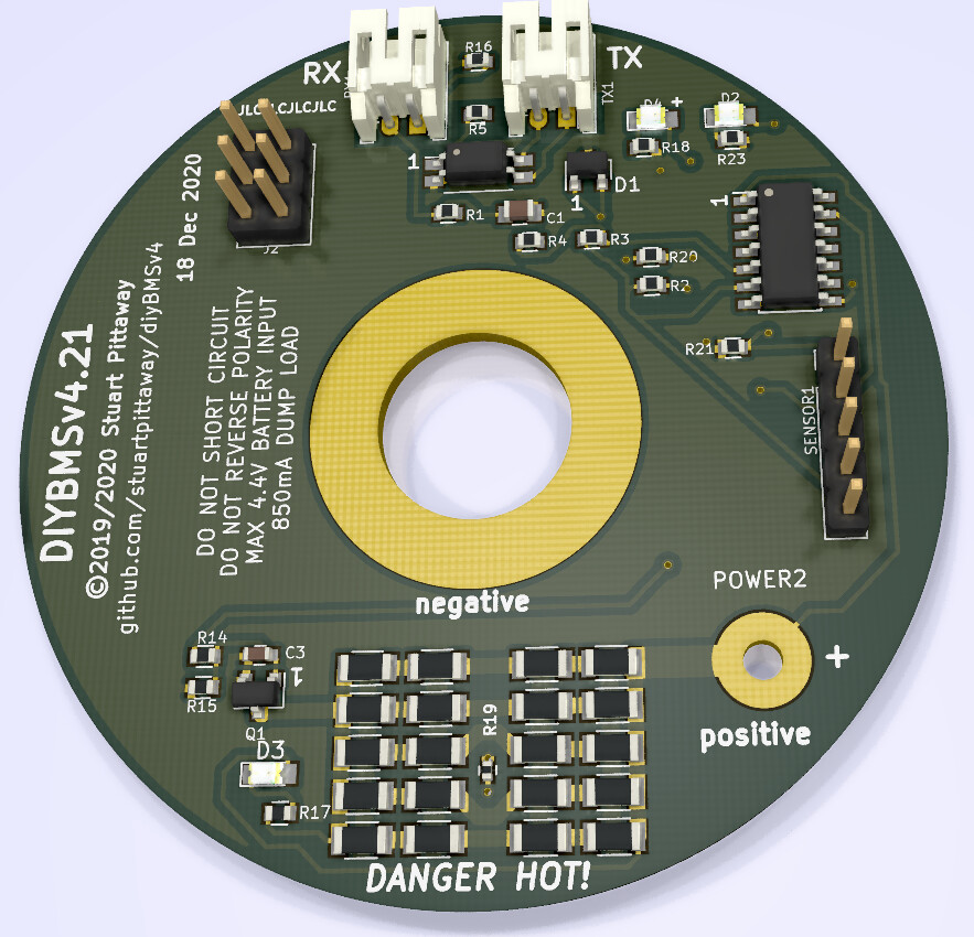
I’m getting quite good at KiCad now! I’m happy to finish off the design for you, but you would be the guinea pig on this, so when/if you order from JLCPCB the design may not work first time (it should) but just so you know…
If you are okay with this, I’ll carry on… I’d suggest lowering the balance resistors to 12.2ohms, that gives 1.2Amp balance @3V. The boards are larger so hopefully heat will dissipate better.
That is not a problem at all. I can’t promise a fast feedback time (the hut is a bit remote so I only go there 1-2x a month) but I can definitely re-order if it does not work right away.
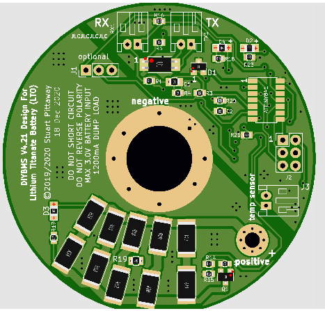
Sounds great! This means you are designing it for the lower voltage of the cells right away, i.e. DIYBMS LTO module?!
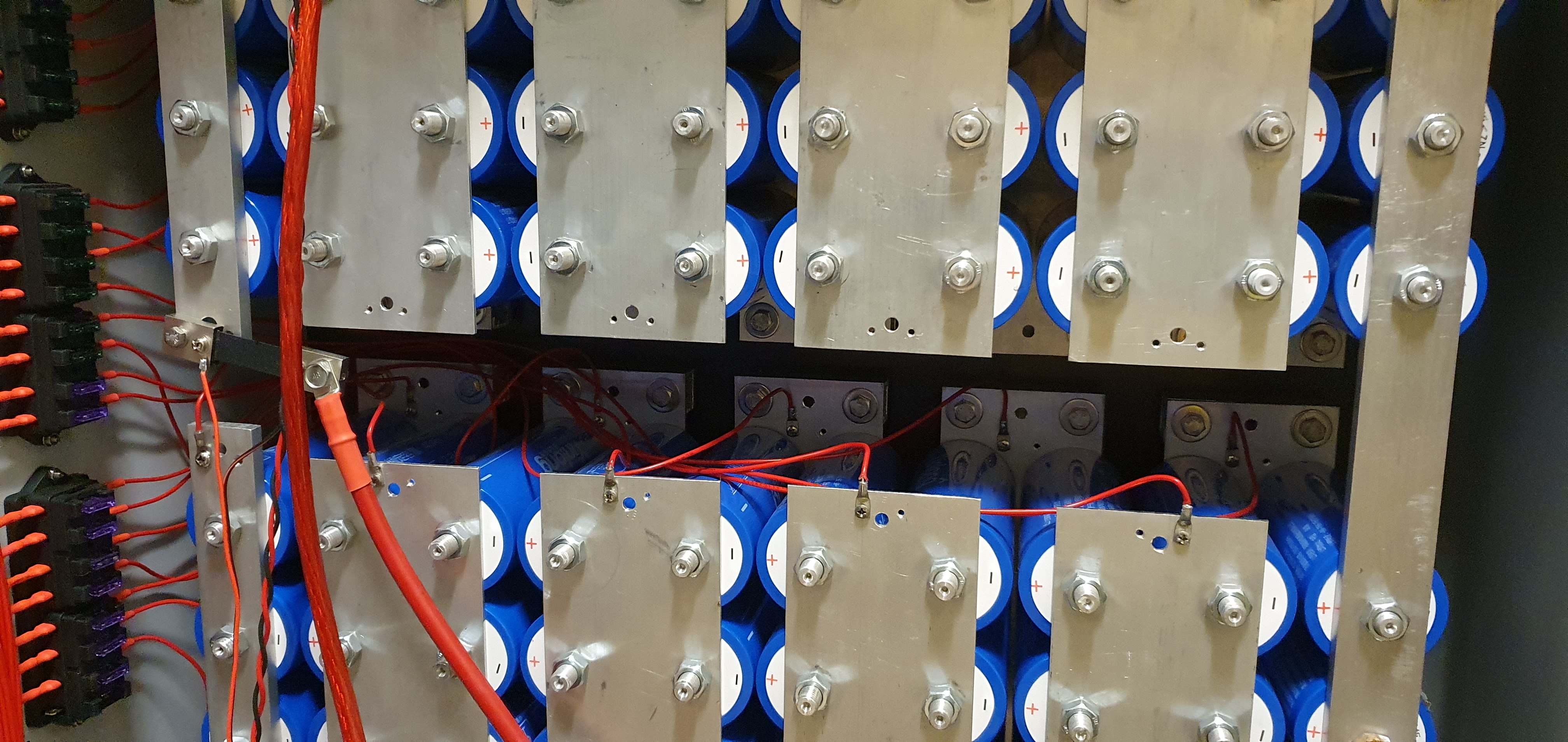
+1, I wouldn’t mind ordering and testing these girls out Stuart, a great idea, could eliminate my cable lengths, but the only drawback for me is with my setup is half the batteries are positive facing outwards and the other half are pointing negative outwards, be great if there was two types, one negative and one positive centre bolt, would probably put a inline fuse on the fly lead that goes to the next battery, I would put a thin copper or aluminium spacer before placing the PCB and then the nut.
I doubt that I would create two types of module in this shape, keeping the existing designs up to date is enough work without extra variants. It would also cost twice via JLCPCB as they charge you per PCB type.
I could easily add a fuse on the positive line on this PCB as there is plenty of room, you shouldn’t need one on the comms cables as these are already opto isolated.
Thermally these should be better than the existing 4.21 design as they are larger and have more copper to use as a heat sink, but you will need that with the higher balance current.
I see they sell yinlong prismatic LTO cells 30 ah for $25 (that have BMS if you want on alibaba.com ) if you did not want to use the cylinder type… but since it a lithium battery there be some special handling charges as there only one port in china you are allowed to ship lithium batteries through. but the cost are not that much as I ordered bulk lithium batteries from china before. when ordering lithium batteries just make sure they shipped and manufactured near that Port of Guangzhou if not as you get caught with in country shipping charges or sketchy shipping practice
Thanks Stuart, I had a bit of restless sleep, last night thinking about ways of going about it… lol, Just a thought, could you make the centre main mounting hole totally isolated , this way it would not matter what end of the battery the BMS was mounted to, a medium sized double or triple PCB terminal blocks for both positive and negative connections and use bootlace type ends on my cabling that would allow extra wiring to other things and also stop the PCB terminal twisting around on it’s self when only on one solder joint only, yes a fuse on the PCB would be a great addition. your thoughts on a greater resistor bank would be a plus
I’ve read that the pouch/prismatic cell type is much less forgiving when it comes to overcharging (the cylindrical batteries seem to handle this much better). To be fair though, one should never even get close to this scenario!
My setup has the back bus bar that mounts the battery to the cabinet, I can only front the pcb to the front of the cabinet, as you can see i have only access the front which has alternative positive and negative faces