DIYBMS for Lithium Iron Phosphate battery cells (LiFePo4) 280aH

Thanks for the advice, didn’t really think about that while I was testing the setup.

hello,

after various tests and builds I’ve come up with two “evolutions” to @Jau design. Evolution is a big word, basically rearranging a few bits to make things happen. Only item changed from his original design is the D1 which is out of stock on JLCPCB. Ah, and added the external TempSensor in a way that it’s easy to cut away but since it’s actually connected with tracks to the ext connector JLCPCB consider it as one board and wont charge extra. Even if you don’t cut it off it will report temps (admittedly quite similar to the internal sensor ones…)

LishenEVE_v1.7ovF

which adds a larger oval on the pads where the battery terminals fit enabling easier 89-91mm spacing and adds jumpers to be able to disconnect the module for updating firmware without taking the whole battery apart.

Zip file to send to JLCPCB (unzip the file and there’s the gerber and the two csvs):
LishenEVE_v1.7ovF.zip (109.3 KB)
and for anyone who wants to play with it the json that loads straight into EasyEDA:
PCB_DIYBMS_LishenEVE_v1.7ovF_2022-01-23.json.zip (119.8 KB)

72-123mm_v1.8F

second version goes a bit further by enabling terminal spacing from 72 to 123mm. Main reason for doing it is that EVE 304 changed to 123mm spacing out of the 90mm and seems to be impossible to know for sure what you’re actually ordering from China… Considering that shipments from there take 2m+ I feel it’s better to be safe than sorry.

Zip file for JLCPCB:
72-123mm_v1.8F.zip (109.4 KB)
and json that loads into EasyEDA for editing:
PCB_DIYBMS_72-123mm_v1.8F_2022-01-23.json.zip (118.7 KB)

NOTE- Missing bits:
ATTiny (as always…)
Q1 Mosfet (tried another one but didn’t work, so has to be ordered separately, it is available and relatively easy to solder)
JST-2-PTH side connectors also missing, easy to solder and decide which side (or one each) suits your setup.

thanks to all involved hope that helps someone!

cheers
V

1 Like

@vas any replacement suggestion for LNG045R210 ?

expecting a new batch to arrive on Tuesday. Let me check if these work (previous attempt with another chip didn’t work…) and I’ll post here.

V.

1 Like

The v1.8 module is working for me in early testing.
Happened to have some Q1 from previous version.
Also found the red LED is now out-of-stock.
Only issue is a bit more clearance on the terminals is needed.
Easy enough to file them out though.
Maybe I should put a bit of heatshrink over all the exposed terminal contact area… bit too easy for me to drop something on that!

1 Like

hello all,

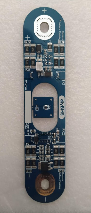
following v1.8 that Andrew was quick to built and test (thanks!) I had more free time and thought of making a 123mm specific version (v1.9) pulling the resistors apart, helping in the pcb cooling as well as leaving a hole in the middle where the venting tab and QR code on each cell lives.
To avoid making the whole thing even longer, I added the ext temp sensor in the middle, easy to break out (or cut with a dremmel) Although I did wire this sensor to the board (so in theory doesn’t look like an individual pcb within a pcb) I was charged some dollars more, I think ymmv.

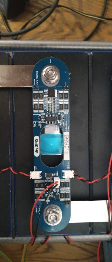
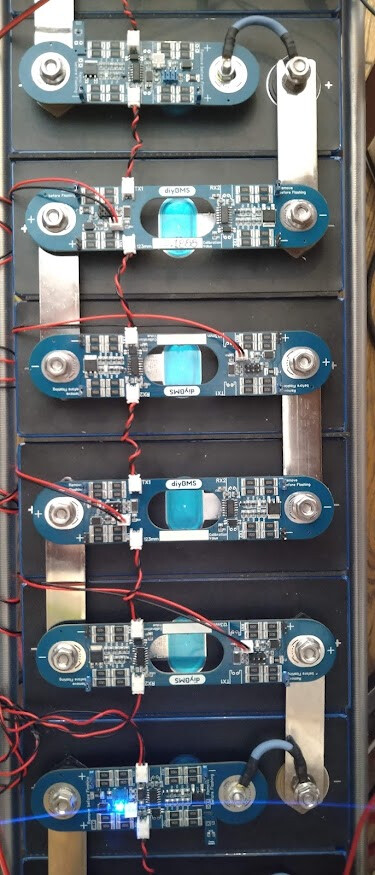
it’s a temp setup atm, once I built the rest, I’ll take the whole lot apart, clean test contact on each tab, shrink wrap the busbars and refit the lot.

@Andrew_Congdon did you test top balancing with these heatsinks on? What Amps will it withstand? Without heatsinks, 1A is the max the system will manage with 65C internal temp without V creeping up. Wonder the new limits! link to the heatsinks you used?
I’d definitely put heat shrink on the exposed part of the pcb, that’s why I did the v1.9 with full width ending so that it’s easier to heatshrink the busbar and keep it covered under the module endings. Note that there’s a thin M6 nut after the busbar and the module sits on top with a locking nut to finish off the install. Easy to replace without disconnecting everything

will post the files later on today

cheers

V.

PS. apologies (in advance) to @stuart as I used the diybms logo. I wont add that on the files I’ll post later. On the back it states the facts as it should anyway!

Those look great!

glad you like it stuart!
tbh honest if the underlying h/w & s/w wasn’t great I wouldn’t go into the trouble to mod @Jau board :grin:
btw, from initial tests yesterday with just one new board, looks like on balancing it stays slightly cooler. Going through another balancing session with the four new boards so will know better later.

That latest design looks really good. Good to be able to easily see the vents.

The heatsinks certainly increase the sustained balance current although I haven’t measured it.
I have a working setup with the old boards and have put them only on the cells which regularly require more balancing.
They allow the 100% PWM indication to be maintained rather than being throttled for temp.
I don’t think they are required and may even mask issues like poor continuity.

I like the double nut idea. I’ve used thin copper washers between the nuts and boards so I can torque down the included nuts and be able to remove them without damaging the board.
My batch of 16 EVE 280 cells had 8 with welded studs and 8 with threaded studs.
I’ll have to measure and see if that leaves the same amount of thread exposed.

Like this I assume?

1 Like

@Andrew_Congdon exactly, thin they are, enough to torque down at this small value at M6. Further means that replacing boards or doing any sort of maintenance doesn’t bring the whole thing down. OK, wouldn’t like to seriously charge or discharge the system at the time, but in an idle/low load state, it should be fine.

Completed some testing with my 8S system where the middle four are the new v1.9 modules and the two on each end are the older ones.(as per the pic I posted yesterday above).
Balancing starting at 3550mV, top balancing with a bench supply where I can accurately tune Amps going in. Bypass overtemp at 65C, room temp 21-22C, results:

@1.2A new modules at 45-55C, old modules at 55-65C Managed to keep that indefinitely - OK, got bored after 20mins but didn’t really look like changing:

@1.5A new modules at 55-60C, old modules at 68-73C. Could not keep it for v.long as old module cells voltage kept creeping up as expected:

interesting to see the influx data in grafana (at 60sec interval though so relatively rough) where it clearly shows the split between the old and new modules internal temps:

Conclusion, looks like the split of the pcb in two parts helps in keeping the pcb cooler (will try with my IR thermometer as well but tbh cannot see that changing!) allowing for a slightly higher balancing current of 1.5A. These tests were done in order to decide on the Victron CANBUS integration Charge Current Limit (CCL). So looks like I’m sticking with 1.5A with no force cooling and heatsinks. May have to reconsider in July Med weather onboard though :grin:

cheers

V.

First a big thanks to everyone who contributed so far.
I am glad i found this because it seems to be the perfect solution for a BMS for my 16pcs LiFePo4 280 AH.

I am about to order the pcbs at jlcpcb.
So far i only found the V1.8 from Vassilis.
Are the ZIP ( or files ) somewhere i did not look yet?
I think i will order it with assembly as i am not so good in soldering the tiny parts.

Thanks again

regards

Joerg

sorry,

was too busy with other things.
V1.9 is 123mm only (ok, holes are oval so got ±0.5mm), built,tested and working fine now for almost two months at my 304 8S setup.
the new Q1 surprisingly is also back in stock!

EVE_v1.9F.zip (121.9 KB)

Note that this design has a “hole” in the middle through which you can examine the vent on each cell as well as read the QR code without having to take everything apart.
This hole has the second thermistor that can fit on the side of the cell. I oversized them to make them easier to stay put with some doublesided or other tape.
YMMV, I was charged extra 8-10usd for them, I don’t mind that, you may be lucky and not charged. BTW, I’ve got tracks from the main pcb to this thermistor board so without breaking it away it will function as second temp sensor (albeit slightly pointless when it is 50mm away fro the pcb mounted one…)
Also note that by splitting the resistors apart, PCB seems to heat less (without heatsinks) so I can sustain 1.2-1.5A balancing at 20C ambient. Guess wont be that high onboard and with 30C ambient.
Final warning since I built my pcbs in blue and I generally avoid green leds, I replaced D4 for a blue led. Easy enough to swap over for a green if you wish on the BOM csv file.

cheers

V.

thanks a lot @vas :slight_smile: when I import the pcb on jlc everything is fine. but afterwards, when I add the BOM/ CPL the parts looks very misplaced on the preview. is it normal? or could you post the “config” nr, that it would be possible to reorder your specific one, but for myself?

thanks a lot

odd, can you please post a pic of the settings screen and where the components are placed? maybe you’ve mirrored something in the settings?

@vas
hey, great to hear from you, thought the same,
and on version 1.8f its looking in preview pretty well placed, but in 1.9f its… messed up, but hopefully, I made the mistake :-).


sometimes I’ve seen this. It looks like it’s different scale, not mirrored.
Try again may work. If you’re brave you can send your order and they’ll figure out the issue and scale/short it as the info is there for sure!
sorry cannot be of any more help (and I don’t even know what you mean by config - don’t think there is one in JLCPCB

V.

hey @vas,
tried to order now the v1.9f but got this reply:

Please kindy add more breakaway tabs with moue bites to avoid the small pcbs falling off during production and the width of breakaway tab is required 5mm at least.

got you have a look? thanks a lot

interesting (not!)
did you use default standards for the PCB?
I mean FR4/Industrial-consumer electronics/1.6mm/HASL with lead/1oz?

judging from the force needed to break out the temp sensor bit, their claim of falling off is at least ridiculous!

hey, I changed it to lead free. this was config.

just tried again, will see