Very strange @Andy
The ESP doesn’t have a dedicated i2c port(s) so you can use any 2 pins.
If you alter the Wire.begin(X,Y); statement you can pick which pins to use - just in case the pins are damaged etc.
Very strange @Andy
The ESP doesn’t have a dedicated i2c port(s) so you can use any 2 pins.
If you alter the Wire.begin(X,Y); statement you can pick which pins to use - just in case the pins are damaged etc.
@stuart I will try that when the temp sensor gets here, hoping this week, never know with AUSPOST.
When i test the temp sensor do i need the pull up resistors. I have been using them on the modules.
I also tried this code too, ESP8266: I2C PORT and Address Scanner : 8 Steps - Instructables.
Andy
Yes always use the pullups.
Has there been any discussion as of yet for implementing:
GREAT project - Cheers!
Hello all,
I am just getting into battery packs. I have played around with the TP4054 modules and they work well.
I am looking into Stuarts diyBMS. What I am trying to understand is how isolation is done between the boards. Looking at the schematic it looks like the ground of the module is connected to the negative terminal of the next higher potential battery pack and the Batt+ is just the positive terminal of the pack.
Can someone explain how this works as the voltage measured is not referenced the cells negative side?
I could have this all wrong.
@stuart
I recieved my wemos mini today and did some testing. Found 12 out of 16 modules, however this is the what i was getting using the bms control tester. I would place a number of scan X like this
![]()
and i was getting this,
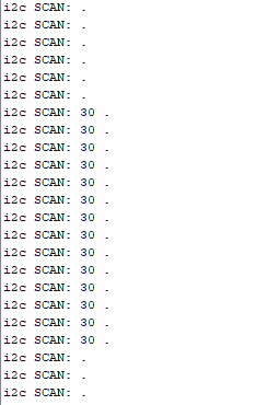
This was occuring on all 12 modules.
Now the other 4, quite interesting they are the 1st 4 modules that where connected to the old controller. This is what happen with the old controller, stupid me had it held by let say a positive pole of one of the battery series. (hard to explain, let say it was bare metal and it was the positive end of set of 18650’s ) i accidental bump the controller and the last 2 pins (Vin and 3V) shorten along the positive pole and the controller blew up.
Any chance that this could have done something to the i2c chips on those first 4 modules.
I have clear the eprom and reset the module to factory setting via the program, then ran the controller test and still couldnt see them. I will do voltage check on modules and see if they are still the same reading, i may have kill some other part of the circuit as well ie thermistor.
Any thoughts?
Thanks
Andy
I suspect it would damage the ATTINY chip rather than the i2c isolator. The only way to know though is to swap one or the other out - quite a pain to desolder them!
@stuart
I will do my voltage checks tonight and let you know. I am not sure if i have any spare components either, so i will have to wait for the long boat from china to get here. I will change out the ATTINY first and see what happens. You are correct Stuart they are a pain to desolder.
Just a question on the circuit, what are we actually doing to the Attiny when we load the code in to it. Trying to understand to help with fault finding.
In the mean time if anyone on here has any spare working V3 boards they are no longer need due to upgrading to V4, please let me know, Not sure the cost to Australia but maybe a good way to recycle old modules.
Thanks
Andy
This is simply configuring the chip with code and “fuses” (settings).
@stuart
Hello i provisioned modules and had them working on the web page today, everything seemed fine. However if i removed the power from the controller or the web page lost connection. The module went into panic mode. Usually i just reset the controller or web page and everything would be back to normal. However with the new wemos nothing is happening, i reset using the resit button, short the rst and gnd as well as the reset on the web page, Nothing happens the string stays in panic mode. Any ideas why?
Also when testing the module using the controller tester, i did a trial of scanning, i would put 10 scans XXXXXXXXXXX and it was only finding about 1/2 on average. I not sure what is happening. Any ideas ?
Thanks Andy
On V3 the modules need the controller to work, so if the controller vanishes (power cut, cable cut) the modules will panic. As you mention, once the controller is back, it should re-scan the modules and return to normal. Does it work okay if you disconnect and re-connect the power instead of pressing the reset button?
Don’t worry about the controller tester if you have successfully provisioned the modules and see them all. If you find the modules dropping off, ensure you have short communciation cables and the right sized pull up resistors installed.
@stuart
So the controller is still not returning the modules back to normal. i tried removing power from controller and then tried the module. Both unsuccessful. It seems like its not scanning, unsure what is happening?
I had it running for 12 hrs yesterday before going to bed. Something is not working correctly as when i woke up this morning, i couldn’t see the data on the web page, refreshed the page, check that the wesmos was being seen by the router, it was, however no data. Then i went to the shed and modules weren’t in panic mode which was strange. They didnt go in panic until i press reset on the web page.
The comms cable are around 150mm and the pull up resistors are 2.2k ohms.
The controller tester is godsend it has helped me so much, i use it all the time to make sure the modules are working correctly.
Andy
Hi Andy, is there a problem with the WIFI ? I’ve got a similar setup with a repeater/router in the garage and it often drops off the network (I can still ping the devices) but the devices attached to the repeater don’t show up.
@stuart
i am not sure if there is a problem with the wifi, its seems to be working. Although everything seems really slow compare to the nodemcu i was using. Its a pain as every time it goes into panic mode i have to do a full factory reset and then provision each module again. Next time it goes into panic mode i can bring a module up to the house and see what happens when it connected directed to the router and not the repeater.
Hi,
Will anyone be selling these on tindie or anywhere, dont have time to do it all myself but would love to have a couple (10 :D)
Regards
I have seen other people mention similar behaviour but I’ve never managed to reproduce it (and therefore can’t fault/debug). Folks have had these DIYBMS devices running in sheds for 12m+ without bother so its it must be down to a difference in WeMos units or similar.
@stuart
Thanks, yeah i am not sure what is happening, i may try and order another nodemcu, but make sure i get one that is similar to the original one i had.
I am wondering is there away to remove the wifi part of the wemos and have it directly connected to a laptop which is then connected to the internet.
How did you get around this problem, as i also have the same issue.
Also which why do you do connect your wesmos, ie to the repeater or router.
Thanks
Andy
Hey all,
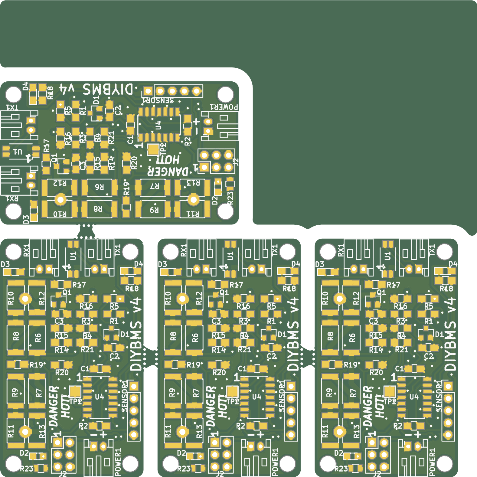
Just found this thread via another forum, I’m about to order a batch of the V4 BMS and so I’ve panelized the Gerber files for V4 to get more value out of the cheap JLPCB (etc) 100x100mm
(effectively you’ll get 4xBMS for your money now).
Feel like I need to squeeze something in the gap, any suggestions for related projects/gerbers that would fit?
Can provide the zip for the panel if you want it for the repo.
Nice work, you can just tick the panel open on jlcpcb and they will do this for you!