I have set in the config file of influxdb:
bind-address = “:8086”
This should allow all sources not only local.
And I have Ubuntu which comes without firewall.
So I stuck!
I have set in the config file of influxdb:
bind-address = “:8086”
This should allow all sources not only local.
And I have Ubuntu which comes without firewall.
So I stuck!
Bear in mind that “localhost” has a meaning only within that physical machine. It doesn’t mean “within your local network”.
So my guess is you must substitute 192.168.178.xx for “localhost”.
ok, thank you:
But what’s the meaning of
bind-address = “:8086”
in my config file?
Should I put my local ip 192.168.178.10 or 127.0.0.1?
I will try out both and check out with netstat.
I am a solder guy not a linux freak 
Me too. So I can’t help with that part. But “localhost” will not even work for me within this machine using Opera browser - I need 192.168.1.xx (in my case) to access a copy website running on here, but it does work in Firefox.
I changed to my actuell ip of my linux pi server (192.168.178.10). Grafana is working after changing from localhost to that ip for the influxdb.
Netstat gives:
pi@bpi-iot-ros-ai:~$ sudo netstat -antp | grep “influx”
tcp 0 0 192.168.178.10:8086 0.0.0.0:* LISTEN 4332/influxd
tcp 0 0 127.0.0.1:8088 0.0.0.0:* LISTEN 4332/influxd
tcp 0 0 192.168.178.10:8086 192.168.178.10:41635 ESTABLISHED 4332/influxd
tcp 0 0 192.168.178.10:8086 192.168.178.10:41528 ESTABLISHED 4332/influxd
tcp 0 0 192.168.178.10:8086 192.168.178.10:41507 ESTABLISHED 4332/influxd
tcp 0 0 192.168.178.10:8086 192.168.178.10:41637 ESTABLISHED 4332/influxd
So I think the server is now listening, right ?!?
But still, esp8266 does not send anything to the influxdb…
Edit: I changed to 0.0.0.0:8086 and now the pi is listening on to every ip address:
tcp6 0 0 :::8086 :::* LISTEN
But still no connection from the esp.
I guess “:8086” is the same as “0.0.0.0:8086” as written here
Okay that makes sense, looks like thats okay.
On a separate device, can you telnet or ssh to the 8086 port and see if it connects.
I didn’t write the Grafana code in V3 (@Colin_Hickey did!) however it uses the HTTP protocol to port 8086, so that looks good so far.
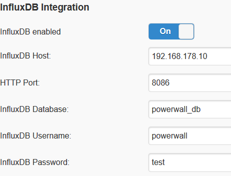
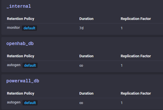
The “host” setting in DIYBMS should just be the IP address, and you also need to provide the database name (case sensitive).
It toke a while i have not yet put some more solder on the chips legs, but did brush them up with the soldering iron. I have 6 board modules ready, the eprom clearing works and i can reprogram the boards, no faults there.
Now when i provision the boards the first one does ok, but the blue led goes on inmedeately and resistor warms up, green led flashing, but not at panicmode speeds, module is shown in wemos webinterface.
But then all leds go out and the green one flickers barely visible, then after a while the blue one comes on again and this behaviour repeats. Now the module doesn’t show up in the webinterface anymore…and i cannot provision the next module (daisylinked)…
Very ocasionally i can provision a second module, but then this also shows this behaviour…any ideas?
I continue testing tomoorow…
From a different linux system (my NAS) I can reach the influxdb by:
curl -sl -I http://192.168.178.10:8086/ping
HTTP/1.1 204 No Content
Content-Type: application/json
Request-Id: c3c23062-acc5-11e9-9c0f-02d40942bcb3
X-Influxdb-Build: OSS
X-Influxdb-Version: 1.7.1
X-Request-Id: c3c23062-acc5-11e9-9c0f-02d40942bcb3
Date: Mon, 22 Jul 2019 21:15:00 GMT
So from this side everything is ok.
Of course I checked all the names, ips etc 100000x times at least.
So at that point it might be a problem in the code on the esp8266.
It would help me, if somebody would send me e.g the influx config file or other setting.
These are my settings at the moment:
Config file:
[http]
enabled = true
bind-address = “0.0.0.0:8086”
auth-enabled = true
Hi,
It doesn’t need anything fancy db wise, i’ve documented my setup in my video’s if you can reach it from another machine it should be able to write to it no problem.
Col
Just in that moment I found out!!!
I had in the influxdb config file:
auth-enabled = true (as recommended in many tutorials)
But the diyBMS code cant handle that. With:
auth-enabled = false
it is working now.
WOW. One day of try and errror.
Thank you for all your help anyway!
Sorry auth was never properly implemented in v3, that one was on me. It has been put in v4 by stuart though i believe.
Col
Hi Maarten,
maybe you have set a value for “max allowed cell voltage”. This is a global value which also is active when you have “auto balance” off. A blue led on and a flashing green LED is normal for the bypass mode.
I guess you have the same problem as I had. I used 2 Ohm resistors. In bypass mode each board draws around 1.4 A. The fuse gets very warm to hot and thus it drops the voltage a lot at one certain point. The diode also drops the voltage around 0.5 Volts. So in consequence the voltage regulator can get a voltage below 2.7 V and thus the system stops working. After a few seconds the fuse is cold down a bit and the module is back.
But I don’t understand why you can’t see the module in the webinterface anymore.
Anyway, start checking the “max allowed cell voltage” setting (set it to 4.2 V for the beginnuing) and the temperature of your fuse and diode.
Also check if you get 3.3 V out of your voltage reg.
Cheers,
Sebastian
Thanks gonna try and meassure things tonight
Hi guys,
Very happy with this forum/project and especially with job @stuart have done.
I made a 7S20P 18650 battery pack and plan to balance with V3 modules and NodeMcu ESP8266 (800ma lm1117 regulator); I already provision one of them and learning in the process.
I want to use OLED i2c display into the rail and include adafruit_SSD1306.h libraries @ NodeMCU. The idea is having OLED displaying module No. /voltage/temperature while they loop (No computer
needed it @ ).
Have any done this within V3 board ?
Thanks!
Due to the hot weather and some other obligations i have not been able tot test this week and will not be able to probably for the next month…  Hope to be back ASAP, cant wait to tinker some more with v3 boards and be able to do some things with v4 boards
Hello All
So here is my current situation, i have my powerwall in the shed, with 14 BMS module connect to it and i have provisioned all the module using my house laptop, using the test controller sketch. I then reloaded the correct controller sketch and i was able to see all modules inside using test battery.
However in my shed i have a stand alone laptop it can be connected to the wifi but the signal is very poor and i usually dont connect it. I want to use it to monitor my batteries but i am unsure how to set up the wemos to do so.
I have tried to run both test and proper controller sketches but i can not compile the sketch keep getting this error message
exit status -1073741515
error compiling for board Node MCU1.0
This is the first problem i need to solve.
When i used my inside laptop and flash the controller and then bring the controller to the shed, i cant find the wemos on the shed laptop and therefore i cant see the webpage.
I really i have no idea how the wemos works. If it has to go to the router first there is no chance its to far away. Some help here would be great.
Thanks
Andy
Hi Andy, the V3 BMS needs the internet for the web interface to work - it downloads libraries and code from there.
Hello Stuart
Which libraries, cant i bring the shed laptop inside download the libraries and then take it back out to the shed.
So the controller can not be setup to do peer to peer.
If i cant do the above how long can i have the control cable to the first module, ie bring the controller closer to the house.
What about putting a repeater/bridge in the shed to connect to both the wemos and the router.
Andy
Yes it can do peer to peer - just setup an access point on the laptop and the Wemos can connect to it.
However you will still need the laptop to have internet access - a router or repeater would work as well.
V4 doesn’t have this issue as all the code is on the wemos.
Thanks Stuart
I think i will go down the peer to peer and i will try and extend the laptop wifi range to reach the router in the house.
Now how to do the access point and the peer to peer, very very limit understand on this side of things. If you point me in the right direction of how to do this that would be great.
Thanks for you all your help
Andy