Hello chitu
Thanks for replying, is there any difference between version 3 and version 4?
It’s a huge difference and not compatible. Different components, power consumption, etc. As @stuart mention is nothing wrong with V3 but the project evolved and in V4 there are more possibilities. I did not build the V4, for the moment i will stay with the V3, but V4 looks very interesting!
hello stuart,
No i solved the temp and voltage problem. I found a short on the actual board and fixed the other short under the resister, so that took me to 13 boards working. I am now trying to get my 14’s working
This a new problem, 2 boards that I measure from gnd to each point on each of the components are the same as a proven good board, but these 2 wont provision. The wemos i working correctly. I have changed U2 several times as well. Thanks Andy
hello Chitu, are they fully completed boards and working and able to be provisioned.
Okay, disconnect all the boards except the “bad one”. Reboot the Wemos (it only scans for modules on power up).
Can you provision the board now? If you can, select “factory reset” for that module and then try it again in the string with the others and see if you can provision it.
Hi
is there a part list available to buy components at one place for v4? lcsc lists doesn’t seems to work in BOM tool
Regards
Software question: If I wanted to make some minor changes to the controller / GUI code, would I end up having to re-provision all the cells every time I flash the wemos?
It depends…
-
If you are only changing the web interface, then no, the Wemos code is independent.
-
If you are changing the way the modules communicate/protocol or if you are moving logic into the cell modules then yes
Obviously if you make some good changes, please let me know so they can be pulled into the base code.
Hi Stuart, hi guys,
I want to give you an experience report about my current v3 build. Just some things I run into and which were not so easy etc. Currently I have done 9 of 14 boards. They are all working now…! 
I need the BMS for a Diy Powerwall made out of 1120 18650 cells connected as a 14s setup. The total capacity is ~10 kWh.
Also I just ordered stuff for the v4. Just for fun 
About the v3:
- I used my 3D printed stencil (diyBMS stencil (v3 and v4) by seba_p - Thingiverse). It really works well!
- I ordered most of the components via Aliexpress. To find the ATtiny85 was more difficult, at least at low cost!
- I used hot air to solder the boards. No problem at all.
- As discharge cement resistor I have chosen 10 W 2 Ohms as I have about 180 Ah (80 cells) in each pack. At 4,1 V (max. setting for me) the current flow will be ~2 A => ~8,5 Watts. Lets see if the resistors are really able to handle 10 W! As backup I have some 3.3 Ohms laying around. Of course I left a couple of mm space to the pcb not to heat up the whole circuit.
- Programming work easily done. But I have done some Arduino projects before. I used an Arduino Nano which I flashed before as ISP. Burning the boot loader and writing the code went smoothly.
- I use a NodeMcu ESP8266 ESP-12E as controller. First I didn’t read about the pull up resistors for SCL and SDA. And ofcourse nothing was working. But 2.2 kOhm between +3.3V and SCL and SDA works perfectly for me now.
- The first problem occured around board 6. First all 6 were running on a 6s test setup. But suddenly one board dropped of. The green LED was flashing showing the “panic mode” then. I couldn’t reset the board as it was not shown anymore. Also reflashing didn’t help. After erasing the flash with the given Arduino expample code and reflashing it worked again. Took me a while to figure this out.
- With board 7,8 and 9 more problems came. After flashing they all showed the solid green LED light. But provisioning didn’t work at all. So I started to reprogramm etc. No luck. After that I started to check the solder joints around the I2C isolater chip. I found out that 1-2 solder joints on each board were bad!!! So I hand re-soldered them. And that was the solution for that problem. I think my 3D print stencil is the problem as not enough solder paste comes through these tiny holes. Also the chip arms bend easly. Thus, they were not touching the pcb. But it didnÄt see it with my microscope.
- The blue LED is very week with the updated 4.7 kOhms in series. I think 1-2k would be better. Or even lower. In earlier versions a 2.2k was given. What do you think?
About the v4:
- I have chosen 5 W 3.6 Ohm cement resistors. I don’t want to have the heat on the board. Once the board heats up, the voltage devider which gives the cell voltage drifts. I tried this with my v3 just by heating the two resistors a bit with my hot air gun (like 80 °C). The voltage reading in the web interface went up about ~0.2 V!
- I hardly found the LM4040BIM3-2.0/NOPB. At Farnell it is discontinued. Finally I fount it on Aliexpress. But 1 USD each and only 10 peaces together. Thus 20 USD for that …

Thanks to all of you working on such a great project!
Best regards from Germany,
Sebastian
Hello Seb
Thanks for your post, you helped me solve of problem i been having. It was point 8, had 3 boards that wouldnt work correctly, everything look correct and was even measured correctly. However your point showed me it could be the I2C chip and its legs, so i pressed down on the legs with my nail and did a scan using the BMS controller test software and finally it showed up. Did the same with the other and now i have spare boards. finally so thank you SEB.
Andy
Ha! Yeah! I saw your post and I was facing the same problem more or less. So I started checking and checking. I couldn’t believe that the solder joints were bad. They looked so perfect.
Glad that I could help you.
Thanks for the great write up and feedback @Sebastian_Nobody highlights the importance of triple checking the soldering just to make sure.
They are expensive, but overall much cheaper than the v3 boards.
Farnell are restocking but under a different part number, no ETA on arrival either.
You can also order directly from Texas Instruments
Hi Sebastian, what do you use for “reflashing with Arduino example code”?
I have provisioned 2 modules which now Stay in blinking panic mode…i AM not sure how get Them to provision ok. But also what to do to the wemos tot prevent this behaviour?
I thought you needed atleast 3 modules for it to work properly!
After reading my previous post I feel i should tell more about “it”. I have a wemos D1 mini pro(with external antenna), programmed and without any modules steady and visible in my wifi netwerk. I have 6 modules, all have been programmed with An Arduino Uno, seems to work ok, after programming the green led status on.
I provisioned 2 modules with the wemos. After that IT looked ok, modules and voltage bar showed up in the interface. But not together at once. They quickly disappeared, leaving those 2 modules in panic mode, flashing the green led.
I can burn bootloader on those 2 modules, and program them again, but when the Arduino is done, the green led does not Stay on, and after 10seconds starts flashing again(panic mode?). Hitting the reset controller button in the wemos web interface does not appear to do anything. I am hesitant to provision the current remaining 4 modules. I don’t know if and how i can reset the modules any further?
Should i reprogram the wemos from Scratch? Or something else?
For me it now appears that the 2 provisioned modules keep going in panic mode even after burning bootlader and reprogramming them and unable tot provision Them from the wemos again? ( Yes i have rebooted the wemos too  ).
).
The remaining programmed but unprovisioned modules give a solid green led, even when not connected tot the wemos, but powered with a single 18650…
I am a bit clueless at the moment.
Maybe i should “burn boatloader” for the wemos and reprogramm that one again?
Hi Maarten,
I hade to erase some boards before I could to a new provisioning. Just use the “example - EEPROM - eeprom_clear” from the main menu and upload it like the normal code.
Beside that triple check all ou solder joint around the I²C isolator. I had to resolder them on three modules!
My main guess is that you have bad solder joint around the I²C, the ATtiny or around the voltage regulator.
Sebastian
Small update:
All my 14 modules are working more or less. The are showing the voltage and the can balance.
BUT: The fuses overheat and the voltage drops down to something like 1 V behind. Thus the regulator drops of and the module stops working. After some seconds the voltage is back and the boards continues. Also the diode gets very warm to hot. I measured the current flow. It is something like 1.3-1.4 A which is more or less as expected with my 2 Ohm cement resistors.
As the fuse is rated for 1.5 A every thing should be fine. But then I lookes in the data sheet:
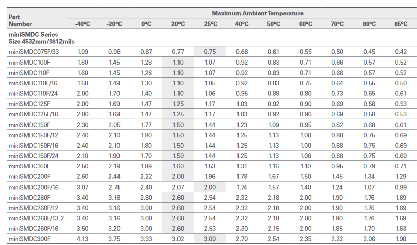
At higher temperatures the max. current is much lower.
So now I changed to a 3.3 Ohm discharge resistor. The fuse still gets pretty warm but doesn’t drop the voltage that dramatically. The current is not at 0.8-0.9 A. The drop over the fuse is maybe around 0.1-0.15 V. But I also checked the drop over the diode. This is around 0.55 V. In sum the drop is 0.7 V.
What resitors are you using?
Are your fuses also get hot?
Should I “upgrade” to a fuse with a higher hold current? Maybe the MINISMDC200F-2 which have a 2 A rating.
But what’s with the diode? Also upgrade?!
Cheers,
Sebastian
Hi Sebastian, the fuse and diode are not required, just there for safety, the boards operate fine if you remove the parts and replace with a wire jumper across the pads. If you do this, remember you have not reverse polarity protection or current/fuse shut off.
Hi Guys,
Next problem:
My data are not send to my influxDB.
My setup.
ESP8266 nodemcu on 192.168.178.59
BananaPi with influxdb, grafana and openhab on 192.168.178.10
I tried to use the same datanbase, in my case “openhab_db” but nothing came.
So I created a second db “powerwall_db” and assigend it to a user “powerwall” with read/write permission. But still nothing.
I never fed data from a different source (ip address) to my influxdb. It was all “localhost:8086” before.
Can it be that linux or influx in blocking my esp8266?
Any suggestions?
Sebastian
Yes - I suspect a firewall is running on the Linux box, or the webserver is only listening on “localhost”.