I figured it out. I turned on the console and was able to see that it was picking up an IP from my router. So I did not have to provide the SSID.
Sounds like you already had another program running on the WEMOS and it remembers the connection.
Please submit the fix into GITHUB - I think others have mentioned this issue already.
The ATTINY chip should program in 20-30 seconds. Ensure you have selected all the correct options in the Arduino editor for boot loader types and device types etc. The correct settings are mentioned in the comments at the top of the code.
i only changed the resitors on my PCB nothing in cod. However i think it still can happen, i will take a look over code and try to cover the case so that modules will still appear in the interface.
Hey @stuart, just bumping my earlier question(s)
Hey just looking through some old posts and noticed this, did you ever get it sorted? You can make it yourself at the site http://solder-stencil.me/ let me know if you need help still.
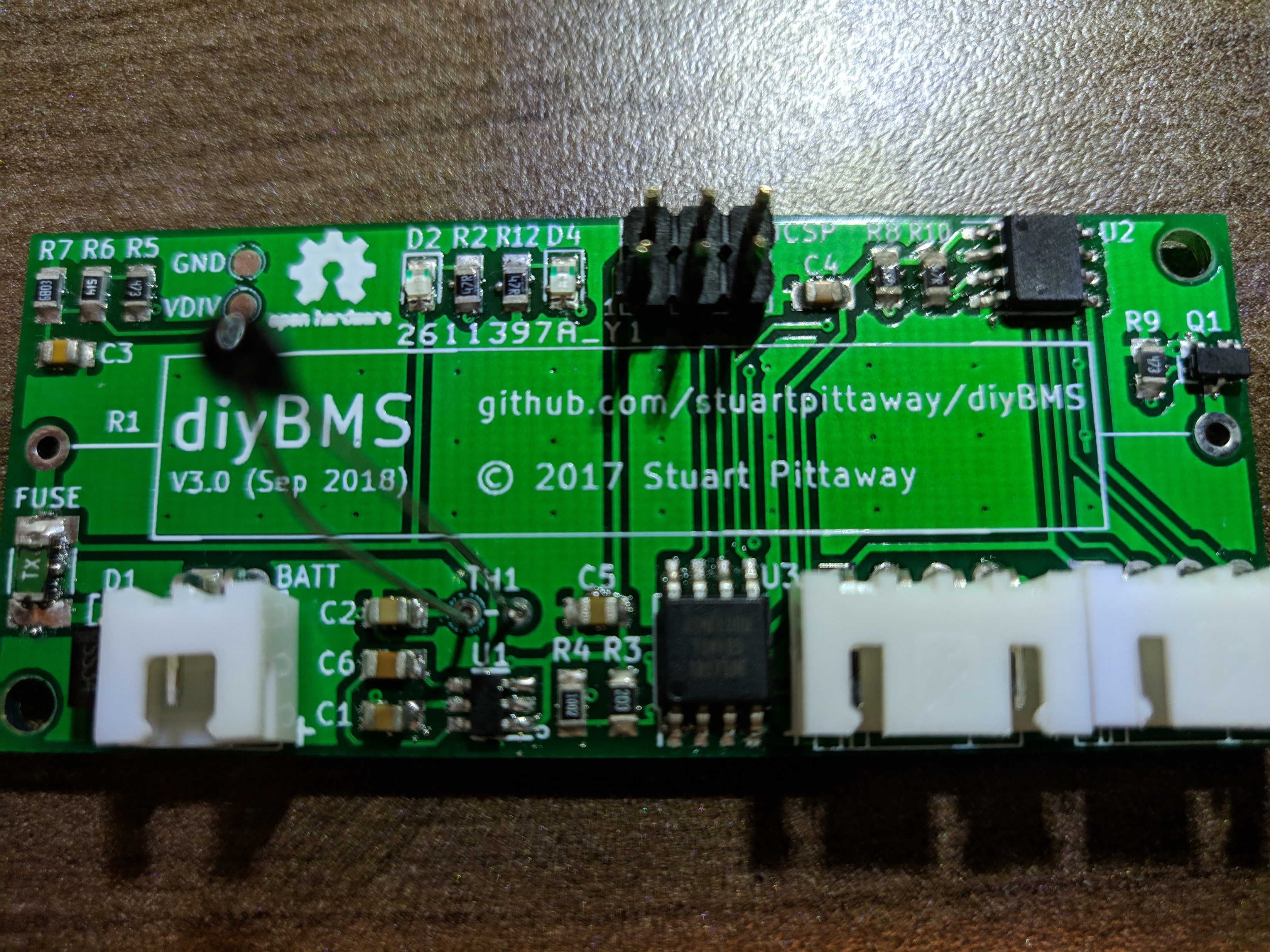
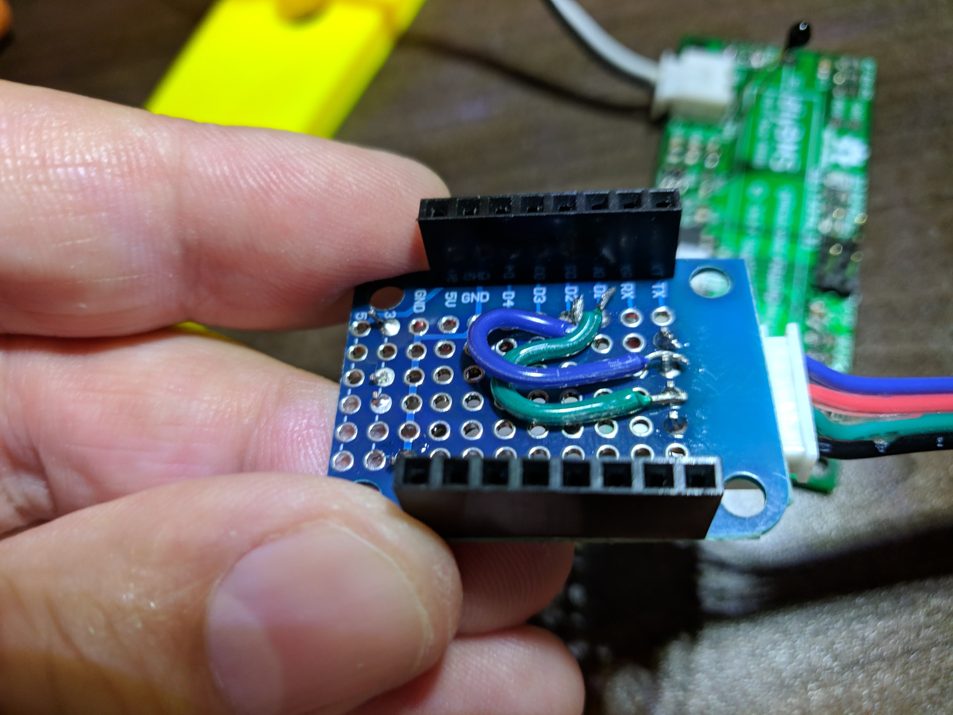
I still can’t provision my first module. I have made 3 boards thinking I did something wrong on the first 2. I have checked all components on the board for shorts and making contact to the pads. Burned the bootloader seems fine. The uploading the code appears to work. LED blinks rapidly for a while then goes solid. I checked the cables from the wemos to the board. I’m getting 3.3v and checked D1 to going to SCL, D2 to SDA. Anything else I can check?
Hi Rick, looks like you have built the boards well and you have checked the basics like 3.3v etc.
What I would be tempted to do is to clear the ATTINY chips EEPROM - its possible the chip thinks its already programmed/provisioned.
Try running code like this on it - https://www.arduino.cc/en/Tutorial/EEPROMClear
After that, reburn the code for the module. Please ensure you have selected the correct settings in Arduino environment.
- 8Mhz internal osc
- ATTINY85
- LDO enabled
Also ensure you only have 1 module connected to the controller at a time whilst you provision.
When you power the module on, it should flash the green LED for half second, followed by a regular on/off flash for an unprovisioned module.
After writing the above, I also realised that I have a Wemos ESP module which seems to have the i2c pins reversed on its PCB!!
Take a look in the controller code for line
Wire.begin(4, 5); //SDA/SCL
and swap to
Wire.begin(5, 4); //SDA/SCL
This seems to be a possible problem between NodeMCU ESP boards and Wemos based ones - although I don’t know why!
Version 4 is almost ready for publishing, you are correct in that the ADUM chip is gone and i2c is no longer used. The bill of materials is also a lot cheaper and the PCB is smaller ![]()
The code has been re-written from scratch for both module and controller. The controller also supports opto-isolated relay outputs and has 4 digital inputs, along with the usual API integration for MQTT and InfluxDB.
Give me a week or two and I’ll get a YouTube video published explaining it all!
I applaud you and also i’m a bit sad about this message since i have my 14s system up and running 
Its the last one I’m doing promise 
Thanks Stuart. When I apply power the LED flashes once an then stays on steady. It’s done the same for the 3 that I have built. I will try the eeprom clearing to see if that works as well.
I tried the eeprom clearing, still no luck. But with all 3 of my boards acting up can you verify I got the right component: ATTINY85-20SU.
I even downloaded all new code from your site. Green led flashes fast while programming. But when I hook a cell up, it still blinks once and stays on…
ATTINY85-20SU should be fine.
Lets try and narrow down any faults in the code. If you take a look at the module code - find the loop() section and add this inside
void loop() {
  wdt_reset();
  ledGreen();  delay(100);  ledOff();
This will flash the green LED for 100ms everytime the loop goes around.
If this works, then we can assume that the code is happy and has left the setup() function.
If this doesn’t work, I suspect that the code is hanging on wait_for_buffer_ready - because for some reason its not reading from the ADC correctly.
Did you try and change the pin configuration in wire.begin in the controller code ?
I did try changing the pins on the controller without any luck. Adding the LED flash did work so we are in the loop. I tried hooking it up to a battery and it still flashes. When I try to provision, I can see the command on the wemo console. So the commands are being sent.
Hello everyone,
I just finished reading all the posts and I would like to congratulate @stuart and everyone contributing to this awesome open project.
I’m starting to build a powerwall and found the DIYBMS v2 then v3, then upcoming v4!
I’m glad I resisted the temptation to order all the v2 boards and components before finishing reading all the posts.
Now I’m eagerly waiting for the v4 BOM 
@stuart is the v4 board using a big resistor? I don’t see any space for it, or do you use a different approach?
Are these boards compatible with 15s packs? I read most of you using it for 7s or 14s.
Thanks!
The boards are using surface mount resistors - balance load is around 800-1000mA. I’ve left 2 holes for a larger resistor to be used if needed.
The boards should work up to 64S (in groups of 16) - although that’s pushing 250VDC+ and I wouldn’t recommend trying that!
It must be an i2c issue - do you have another WeMos board you could try?
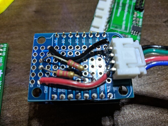
Are the pull up resistors too high/low in value?
I’m using a 2.2k resistors on the board. I even made a new cable and tried it without any resistors. I only had a wemos lite and that would not provision a board. If I have any resistors or caps out of place on the board or wrong, would that make a difference. For example, I did not use a polarized cap for C5, just a regular .1uf? I’m at a loss! I have tried all the suggestions on the 3 boards I have built with the same results. Should I try different resistors on the wemos?


