No problem! At least now we are on the same page in terminology ![]()
I did not - but thank you for explaining. So when it comes to relying on measurements for cleaning up the last little bit of phase error, you’re saying to not rely on visual comparisons of the waveform at all, but instead to tune the real power value I’m calculating to that of a meter?
On that note, I don’t think I should be using my electric space heater as the load I’m calibrating against because it has a fan. Should I instead go buy a high power halogen light bulb (~600W), and try to fit as many coils in my clamps as I can? (edit: I bought one)
I had experimented with this in an earlier iteration of my code (here), but at the sampling speed I was using, it was too large of a correction. I also didn’t have the understanding that I have now. Plus, now that I’m sampling over twice as fast as before, I will absolutely try this again… if this works, it will be a lot less work for the CPU than having to rebuild 5 individual wave forms (equiv. to 10K calculations!). If I read the voltage first, then CT0 - CT4 next, maybe this strategy won’t work for CT0, but it might for CT1-4.
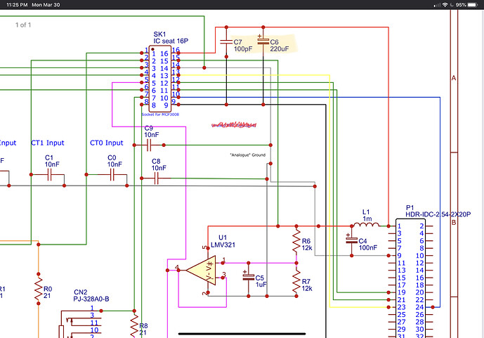
I will have to work this out on paper so I can understand it better. My initial thought is that I can think of each set of current samples aka batch is taken either 1, 2, or 3 sample intervals behind or ahead of the voltage sample. To help demonstrate my thought process, I added a Time Shifts Needed column to the table I previously shared:
| Sampling Order | Time Shift Needed | Equivalent Phase Error | PHASECAL | Time Shifts Needed |
|---|---|---|---|---|
| ct0 | 3 * 32µs = 96µs | 96µs / 46µs = 2.08696° | 1.5 | -3 |
| ct4 | 2 * 32µs = 64µs | 64µs / 46µs = 1.3913° | 1.3333 | -2 |
| ct1 | 1 * 32µs = 32µs | 32µs / 46µs = 0.69565° | 1.1667 | -1 |
| AC Voltage | 0 | 0 | 0 | |
| ct2 | 1 * 32µs = 32µs | 32µs / 46µs = 0.69565° | 1.1667 | +1 |
| ct3 | 2 * 32µs = 64µs | 64µs / 46µs = 1.3913° | 1.3333 | +2 |
So, I have 5 pre-determined values for phasecal for each sample, depending on when in the sampling order the actual reading happens. For example, ct0’s batch of samples will need to calculate real power using a voltage wave that has been shifted backwards by 3 sample intervals (plus the actual phase error correction).
CT4’s batch will have to use a voltage wave that has been shifted backwards by 2 sample intervals, plus the actual phase error correction.
…Etc…
Maybe I can combine the two correction strategies and create one re-calculated (using phasecal) wave that is 100% phase corrected for a single CT channel, and then compare the rebuilt wave against the other CT input channels and see if the shifting technique works well enough for them.
At least now I have the understanding to experiment with various options! Thank you.


