Just saw it and wondered what it was and what the significance of it is.
And then you linked me to an article.
Didn’t understand it and then looked up power factor.
That is what the Shelly instructions says it does, applies a correction factor to the measured power.
Power Consumption
This is the power which is actually consumed or utilized in an
AC Circuit is called True power, Active power or Real power.
It is measured in kilo watt (kW) or mega Watt (MW). It is the
actual outcomes of the electrical system which runs the electric circuits or loads. This is the energy which you are paying.
It is shown in blue color in the history graph.
If you have solar panel and sell energy, you will see this power
with “negative” value. It is shown in green color in the history
graph.
Reactive power:
This is the power that flows back and forth, it moves in both
the direction in the circuit or react upon itself. The Reactive power is measured in Volt-Ampere reactive (VAR), Kilo
Volt-Ampere reactive (VAR) or Mega Volt-Ampere reactive
(MVAR). You are not being charged for this energy.
Power Factor:
The power factor of an AC electrical circuit is defined as the
ratio of the real power absorbed by the load to the apparent
power flowing in the circuit, and is a dimensionless number
in the closed interval of −1 to 1. A power factor of less than 1
indicates the voltage and current are not in phase, reducing
the instantaneous product of the two. In a perfect situation
the Power Factor is close to 1.
Voltage:
Voltage, also called electromotive force, is a quantitative expression of the potential difference in charge between two
points in an electrical field.
You can download your history by going to https://my.shelly.cloud/ in a browser on a PC
That’s all correct. A low power factor is bad news, because it means more current, hence thicker wires and bigger losses for the same real power (or active power is it’s sometimes called). The power factor can be leading or lagging, usually lagging, depending on whether the current wave is ahead of the voltage wave or behind it. A power factor of zero means a lot of current but absolutely no useful power.
If you’re an industrial consumer, you’ll probably be surcharged for vars, because they cost the supplier money in fatter cables and bigger transformers than would otherwise be needed.
You can probably see your power factor on your smart meter.
The amount used/paid for or the amount that is actually useful and gets to the device it is connected to?
I assume that my SM120 meter reports what I am actually drawing from the grid and paying for and takes no account of power factor, that is, it doesn’t reduce the reported consumption to show what the device actually uses?
It’s useful to know this for comparison purposes.
I often wonder why I cannot get my heat pump power consumption down as low as I see on some other similar heat pumps.
It would also explain some other discrepancies that I see when looking at some heat pumps monitored in different ways to mine, for instance, some large swings in the COP when nothing is visibly changing very much.
I assume it is the power factor changing with varying loads, it would explain what I see on some data.
Those two should be the same thing. In the UK, domestic consumers pay for real power.
No, you’ve got the basic concept wrong. It does report what you’re drawing and does take account of power factor and records what you’re paying for.
Are you thinking watts = amps × volts? If you are, this assumes a power factor of exactly 1 and for an immersion heater or an electric kettle, it’s true. For anything else - say a computer power supply, it’s not true and the power factor explains the difference. Power Factor is defined as the ratio (real power) / (apparent power), or if you like (real power) / (rms volts × rms amps). So amps × volts will always be equal to or greater than watts.
Yes, that will happen. But you’ll only see it if you’re able to compare real and apparent powers at the same instant. A small induction motor (e.g. a fan heater on cold) will have a p.f. that’s quite low, probably 0.7 or even lower. LED and fluorescent lamps can have pretty poor power factors too. But your induction motor in your heat pump will be run off an inverter, and that will almost certainly have internal power factor correction and be very close to unity.
Did you mean post no.266?
Clearly no p.f. correction on that one. That’s not too bad for a p.f., but it could be better. It means the rms current is 333.14/(246.01 × 0.81) amps – 1.672 A, rather than 1.354 A if you just divide the power by the voltage.
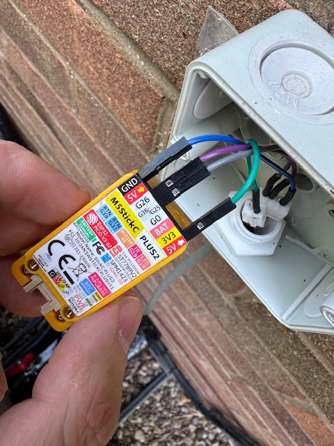
Right, I have my M5StickC up and running and hooked up to HomeAssistant; I only now need to actually connect it to the serial port on the heat pump and away we go.
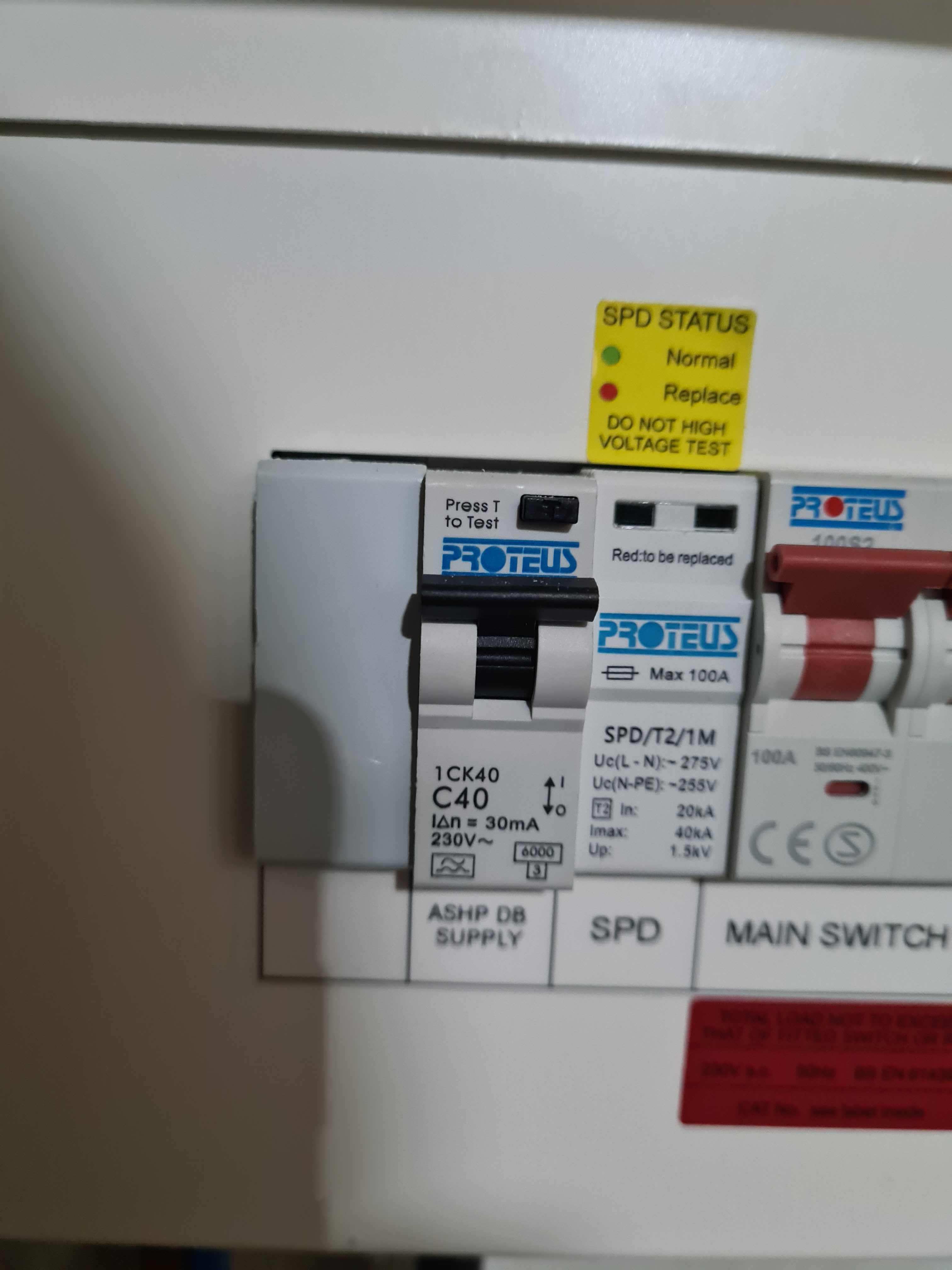
Regarding the Shelly EM; there’s no space in the outdoor distribution board (there’s one RCD it that for the HP and another for the BUH), but inside the house there is space - see photo. Is it OK to use this instead - it would mean I can’t monitor the BUH use - only the entire power draw - but is that really an issue?! Does the UK ever get cold enough to use a BUH?!
Hi All,
Long time reader, first time poster, total n00b
I’ve been following with interest since this was first posted, and only just getting round to installing the ESPAltherma on my EDLA11DA3V3 11kw Daikin (300lt tank) unit as its getting its first service next week. Local firm so no issues in putting it in, they are interested.
From a purely hardware query, I have my shopping list from the posts, there is an issue with the M5Stick and the unit acting as a faraday cage. Having no skills and no tools I can’t crimp cables.
However, can I run a Cat6 cable from the M5Stick to my home wired Ethernet port near by (is that what you call it? We got the house wired as we work from home) as I can run it along the ASHP pipework and into the house. A small drilling job that I am capable of..
Is my understanding correct that this would let me leave the M5 in the ASHP and collect data from my Green HA box, into HA and then try and get everything online (a later battle)
I would then get a Shelly EM3 50A and get the electrician to connect it up to have energy monitoring, though this will come later.
I’ve read the thread multiple times, and just can’t quite pin it down and likely got it wrong
Also to power the M5 I’d need another similar length USC cable run to the house? Or does the ASHP power it through the Dupont wires?
Many thanks. Amazing thread and info, I’ve learnt so much, and continue too.
The M5Stick doesn’t do Ethernet, only WiFi. Although there are other M5Stack units that do e.g. M5Stack ESP32 Ethernet Unit with PoE - The Pi Hut, that one doesn’t have USB to make the programming simple. This unit RJ45 Ethernet Development Board (ESP32-S3) - The Pi Hut does have both USB and Ethernet. However, the ESPAltherma code would need changes to support Ethernet - it’s a different API from the WiFi. I haven’t looked at this, but happy to. The ESPAltherma code runs on a standard ESP32 as-is, otherwise I believe.
The good news is that any of these can be powered from the port on the ASHP - it has Gnd and 5V, which can be attached to the ESP32 to power it.
I’ve looked at the ESPAltherma repository, someone has already made it work on the M5Stack POE unit, but I’m not sure at this point how they got the code onto the device. It also took some GitHub work to get a functional codebase, as the changes haven’t been incorporated into the mainstream yet.
Thanks for the insight John, much appreciated.
I’ll give the M5 a go and see what happens. The Google puck is barely 4ft away, thru glass, so there’s hope. I’ve seen a booster aerial in some installs as well, so that’s an option.
Not heating season yet, so still time to tinker before data time. Gives me time to learn more HA as well.
I’ll let you know how i get on
If you can get the M5 outside the HP case in a waterproof box, it could work very well. The cable can be a few metres long especially if it’s shielded. The M5 won’t take an external antenna.
I’ve lurked for a long time but thought I would sign up to try and help you with this. I also struggled to get my M5 stick to get a WiFi signal inside the heat pump case, and in the end I ran an Ethernet cable into an outdoor rated enclosure where it’s happily lived ever since.
Now I was fortunate enough to have the cable professionally soldered at each end, but in hindsight this was a waste of time - it’s quite straight forward to strip a little insulation off each end of the Ethernet cable then use wago connectors to make the connections to some jumper cables.
Hi Ben. Thanks for the input.
I’m going to have to try and simplify it a bit for my brain, but I think I have it.. (Thanks to 1st review photo on the PiHut for the M5StickC5Plus)
You are using the Ethernet cable as a replacement cable to connect to the X10 connector port and the M5stick, yes?
Snipping the end off, then stripping the Ether to get a wago on it, plug into the M5, do the same on the other end of the Ether with multiple wago matching the colours to the Ether and colour connecting Jumper wire broadband cables, to plug into the X10 port. It seems there are only 4 colours going by @Stephen_Crown original posting, so just these colours at both ends of the Ether?
This then gives you the length to mount externally in a weatherproof box by running the cable, it seems, through the space/hole in the bottom of the Daikin, to the closest side to the WiFi puck
If this is right, is it simply a case of colour matching the cables each end so it works properly?
Or is there a guide I can use? I’ve haven’t come across anything yet.
This is something I feel I could do if I’m correct in my thinking.
Hi Brendan, I think you’re 90% of the way there in your understanding
Step by step, the process would be something along these lines:
Get Ethernet cable, cut an appropriate length. I used approximately 1.5m - this was a little excessive but it’s not a big deal since any extra can be hidden inside the heat pump.
Pick 4 colours, strip back the insulation and install a wago connector at each end. I’ll leave suggesting an appropriate connector to others, since I didn’t use one myself and I wouldn’t want to get it wrong. Note you can use a single strand from each twisted pair, no need to use both.
At the other side of the wago connectors you want to install jumper cables. You’ll have to cut off and strip the insulation on one side for each, giving you female connections for the X10/HP side and male connections for the M5 side. I used these: Amazon.co.uk
Optional, but at this stage I would get a multimeter and test continuity for each wire before going any further.
Now you can open up the heat pump and plug your cable into the X10 connector and thread it through the grommet above the circuit board, then down and out of the grommet at the bottom of the unit next to the return/flow pipes.
Thread your wire through the gland (you might need to unclip then reclip the wago on Ethernet side for this step) and plug it into the M5 stick
Stick the enclosure onto a surface. Number of options here, the most professional is probably screwing it onto a wall, or using magnets to stick it onto the back of the heat pump case. I’m not professional nor was I smart enough to think of the magnet idea, so I used double sided gorilla tape to stick it on my wall.
Brilliant Ben! Thanks so much.
All this bodging we all do just to get some usable data out of the damm thing!
Hopefully Altherma 4 users won’t have to go through this.