Daikin 9kW ASHP application discussion

I know, I have seen your picture somewhere else.

I think there is something to be gained by insulating and I can’t see any harm in doing so, some of it is already insulated, and not in a particularly special way.

I think it is important to consider very carefully what is going on.

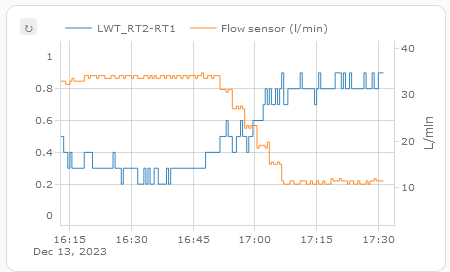
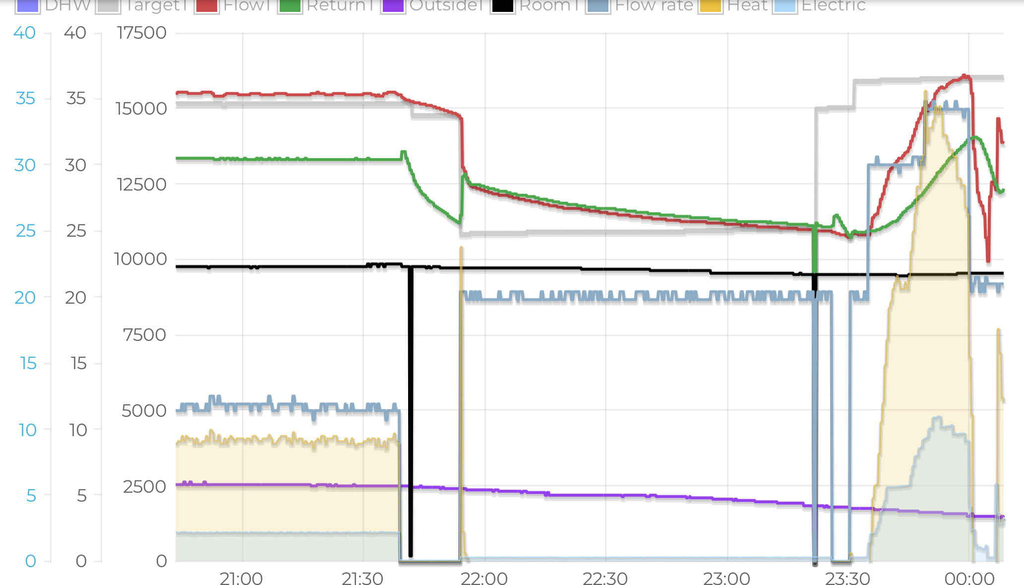
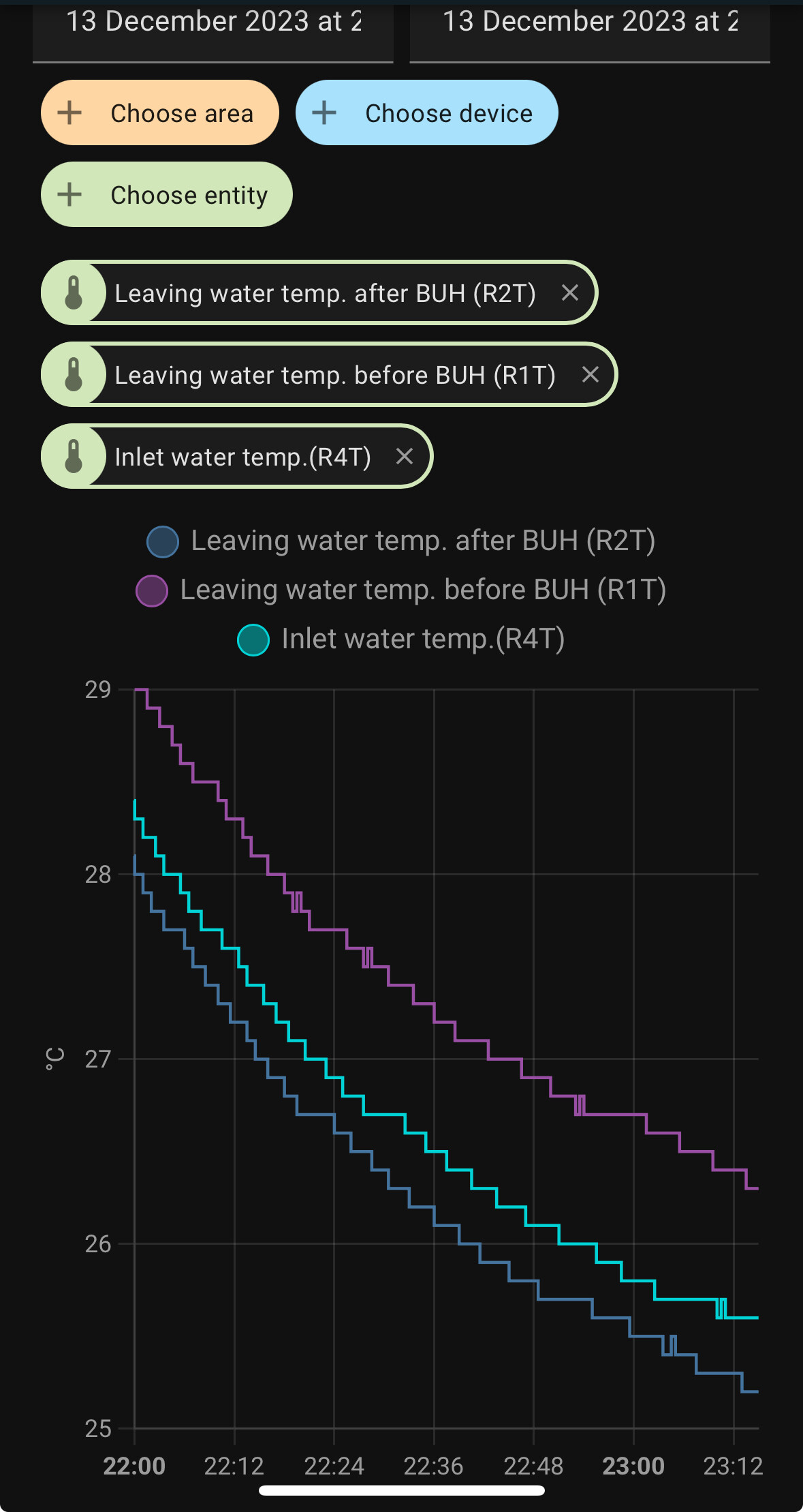
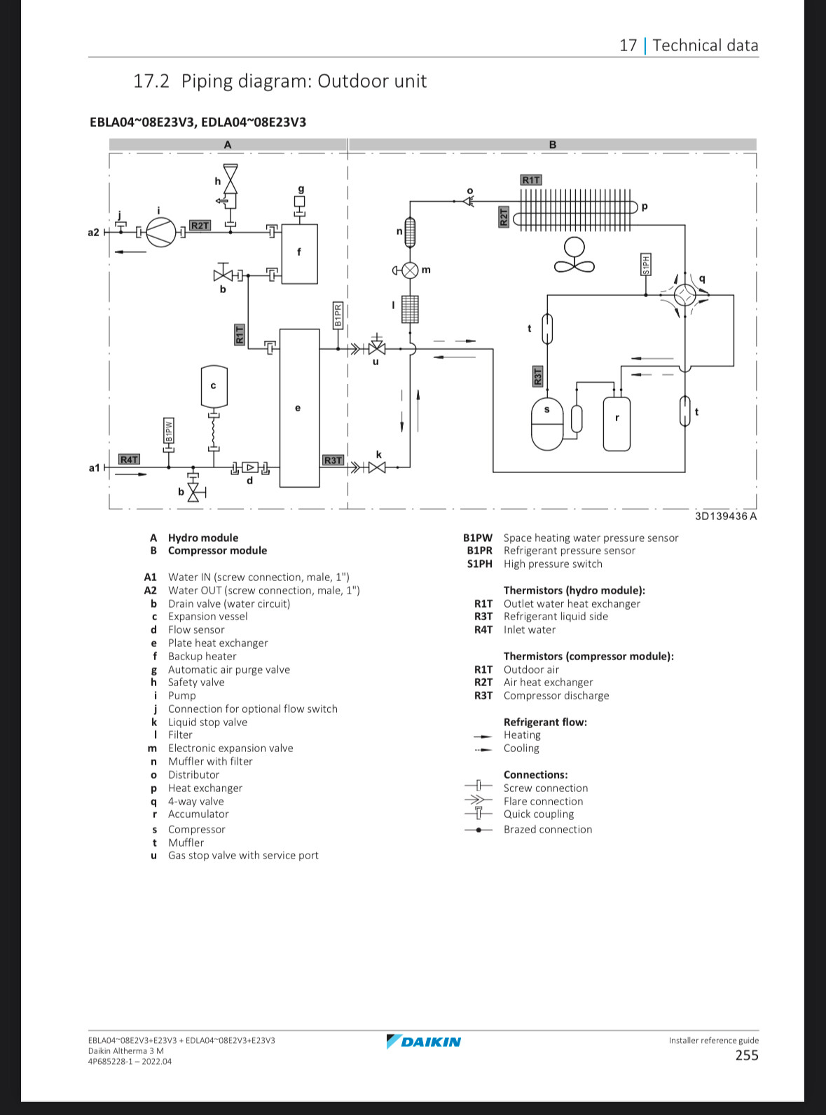
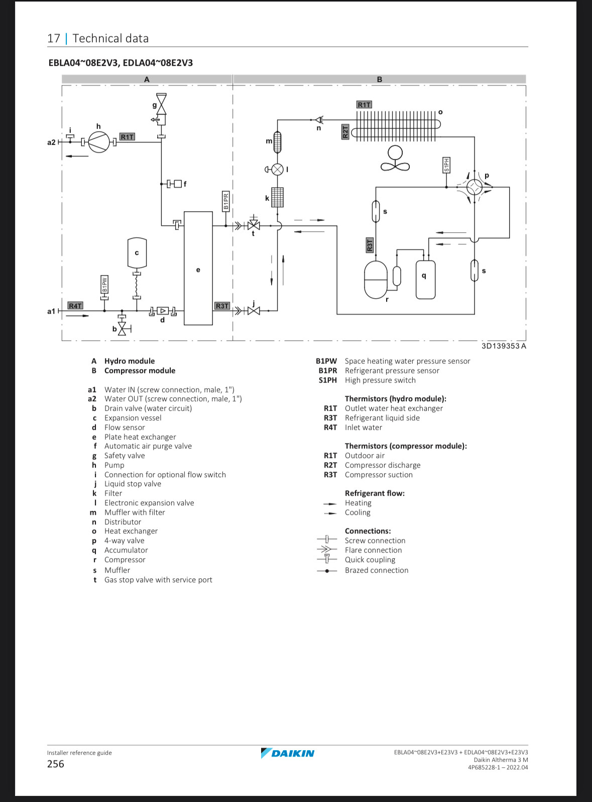
In my case, and I would expect the same in all other cases of this heat pump with a BUH, R2T is the LWT coming into the house.

There is a higher water temperature at R1T but that is not where it leaves the heat pump, it is where is leaves the heat exchanger.

We could reduce and possibly eliminate the heat loss between R1T and R2T but it won’t make the temperature at R2T higher, it will make the temperature at R1T lower.

That would be a good thing at anything over minimum electrical input as it will improve efficiency.

Insulating those pipes between R1T and R2T won’t increase the temperature at R2T though as R2T is the LWT requested by the MMI and delivered at the outlet of the heat pump.

In my example when R2T is 35.0c and R1T is 36c the saving and increase in efficiency, if we were able to eliminate the heat loss in full, would be the additional electricity required for the heat pump to produce water at 36.0c instead of 35.0c

Somehow I doubt it is very much electricity in reality, which is perhaps why it is constructed as it is.

I’m sure we could work out how much electricity would be consumed by the compressor in raising the water temperature by 1c at a flow of 11 lpm at a COP of 5, probably not much, the loss is pretty small in reality.

The actual loss in efficiency caused by the temperature drop is nothing like the apparent heat loss shown by using R1T as LWT instead of the actual LWT at R2T.

The heat pump is not using 14% more of the total reported electricity consumption (as the electricity use includes other things like the circulation pump) to heat the water to 36.0c instead of only 35.0c

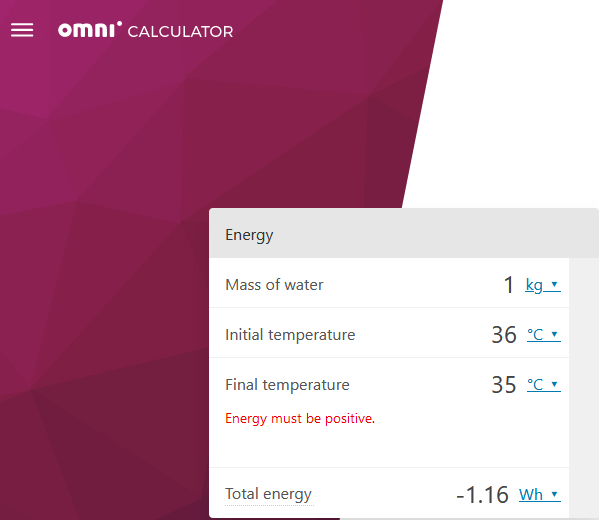
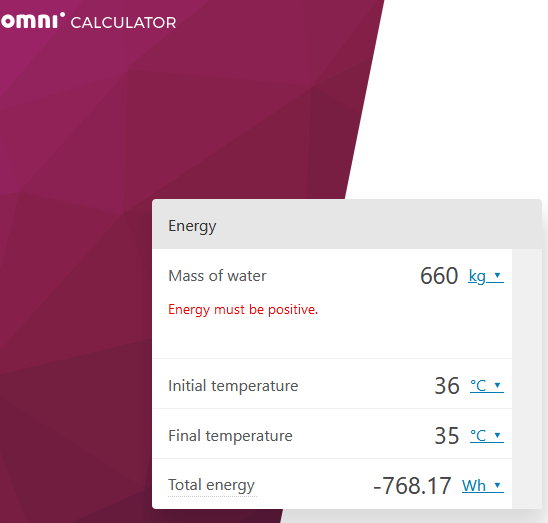
It takes 1.2w to increase the temperature of 1 litre of water by 1c

So if the flow rate is 11 litres per minute the heat loss between R1T and R2T needs an extra 792wh of energy which at a COP of 5 is electricity consumption of 158.4wh.

Quite a lot really.

Is my maths correct?

Checks out (although you have a typo - it’s “1.2Wh” not “1.2W”, but i’m sure you know that)

1.2Wh is close enough (1 litre of water = 1kg):

11l/min is 660litres in total, and as such comes out at 768Wh, which I agree is…a lot.

Just to provide another data point, here is the last hour ΔT between LWT R1T and LWT R2T on my system plotted against flow rate (I’ve just come off Octopus Power-Up free elctricity session where I handily for this test boosted targetTflow into the low 40’s from being off all day)

You can see there is a drop of ΔT when flow rate steps up a gear.

image

Hi Stephen,

I’m not sure it’s a typo, just stupidity!

It’s unfortunate that there are two versions of these heat pumps, those with BUH and those without.

R1T is the only place to take LWT from if you have and non BUH model.

In BUH equipped models R2T is the LWT.

R2T is always the same as reported by my heat meter and it is the same with @ColinS heat pump.

My R1T temperature is higher than the R2T as yours is and @John , but I can’t use the R1T temperature to calculate the heat produced because it just isn’t true, it is higher than what is coming into the house.

I don’t see how the temperature reported at R1T can fall as it passes through the BUH and then rise again after passing through R2T with no energy input, mine does not do this.

R2T is the LWT requested by the MMI, the fact that R1T is higher is a concern but not relevant to the calculation of heat produced.

If we can get R1T close to R2T then we should use less electricity.

I see no harm in adding insulation to try to get R1T closer to R2T.

I am so tempted to do it but I am interested in other views first.

No-one is disputing the use of R2T sensor is the “most accurate” via the onboard data (vs a MID Heat Meter which of course is going to be “correct”).

I’ve even raised this on the ESPAltherma GitHub to get the documentation updated to reflect this, and have clearly labled the “My HeatPump app” to state i’m using ESPAltherma and via R2T sensor.

I think the issue we’re trying to delve into, understand more and ultimately figure out why, is where on earth is this heat energy going?! If we add insulation, the hypothosis goes that we should as you rightly state see the ΔT drop between the 2 sensors.

I shall be adding insulation, I don’t see how it affects warranty if done carefully and pragmatically (i.e. there may still be areas not able to insulate safely).

Yes, I saw the GitHub post (an unfortunate name!), and no answers,

The energy can only be going one place, into the atmosphere!

I am going to add insulation of a good quality.

There is already some insulation there but it doesn’t look particularly special.

I cannot see any harm in doing so, it is not hot in there, nothing is hot, and as long as it is done carefully I think we should see a benefit.

The only downer that I do have on it is that when we are at or close to minimum electrical input there will be no benefit.

This is my problem with this heat pump all along, it doesn’t matter how low you you go on the flow temperature, there is a floor for electricity consumption.

I know that all heat pumps are the same but for my 9kW version the floor isn’t particularly low.

But enough of the negative waves! Who knows what we will see, it could be good.

Edited, I have just bought some insulation.

1 Like

I think a good experiment to do is to run the pump without the compressor, and plot the three temperatures. E.g. at the end of the day when heating is on set-back.

There will be very little heat loss as the pipes reach ambient temperature, even if not insulated. They ought to converge towards the same point as the system cools. Any difference between then could be attributed to measurement errors.

2 Likes

That’s a good idea! I’ve worked with temp sensors in parallel before and calibrating them against one another is always critical. I’ll work out when to try it out :-). Thanks - lots of sense from Tim, as usual.

@Timbones in theory I’ve just turned mine off @ 21:40 on December 13 2023, and changed the pump configuration to “continuous”….and turned space heating back on at 21:53

Got until 23.30 when off-peak kicks in space heating on again…

Let’s see how it goes. I’ll share the dT of R1T and R2T tomorrow here.

I have finally got it running at a COP of 5+

The trick was to open my windows!

Who needs a Madoka when you have windows :slight_smile:

Increasing the heat loss got me a COP of 5 at the minimum electrical input.

The heat pump has been running well today and stable. I now know that the first hour of running from cold uses 1.5kWh of electricity.

So I can run it for twelve hours for 18kWh of electricity, one hour on, one hour off or I can run it continuously with the windows open for about 21kWh allowing one hour for DHW.

Hopefully when I have added my office to the system I will be able to run like this without the windows open.

1 Like

Hi @Stephen_Crown - how did it work out? I’m also tracking R1T-R2T and mine does’t really change from 1.9-2C apart from when the pump cycles, at one of those R1T < R2T briefly!!

A few days late:

dT between R1T and R2T for the time window referenced:

EmonCMS view of same period:

Link to view above:

https://emoncms.org/app/view?name=9ChurchStreet&readkey=53fbf32311dcafcbf15209adc8e10c7f&mode=power&start=1702500200&end=1702512510

It’s consistently out, but even flow and return don’t converge. :thinking::weary:

(Could this be the 40m2 of UFH that is 80mm deep screed pulling some heat back out?)

Cc @John

Looks like you might need to add a calibration offset to the R2T input to emoncms, perhaps +0.3°C.

R1T is persistently 1°C higher, so maybe subtract one from those values.

1 Like

Matthew’s system (which uses OpenEnergyMonitor sensors) shows a nice correlation between flow and return while the compressor and pump are off, which is what I’d expect to see:

Thanks @Timbones! I can only say “duh!” in the light of my assumptions about sensor accuracy! @Stephen_Crown, I’d suggest adding a section to the ESPAltherma/HA topic about the need to “calibrate” the R1T/R2T/R4T sensors with no heat input before relying on them.

On which subject, I’ve just turned my HP “off” - Onecta On/Off to Off for Space heating, set the circulation pump to continuous ([F-0D] = 0). Although the HP is not generating heat, from the electrical input the circulation pump isn’t running either. Any ideas on how to make the circulation pump run when the HP is not On for Space Heating?

Edit: Turned HP back on, but setback -10C, so TargetT well below current R1T/R2T. Let’s see what happens.

1 Like

@Timbones did you mean pump off? I’d say that looks like pump is set to continuous from the graph.

Other point on my figures is pump speed on sampling (ie compressor not running) is 60% of max pump speed/power.

@John I did the same, don’t worry :wink: :man_facepalming:t2:

Yep, once we’ve got to the bottom of this I will. There is a general caveat point added there already for now.

Of interest, The smaller Daikin Altherma unit (4/6/8) without BUH that @jtrent has now setup via ESPAltherma and HA has R1T in the same place as R2T for the BUH model from the schematics:


I did. The flow rate drops to zero at 13:12.

1 Like

I’m confused! The test myself and @John are carrying out are with a reconfiguration to enforce pump running continuously….what have I missed on this one?! :weary:

I suggested to keep the pump running to ensure that the two readings are as close as possible, as there’s only the heat exchange and BUH heater between return and flow.

The chart I showed above wasn’t run as an experiment, just a section I noted during normal operation. The pump was running at the start, which brings the temperatures together at least.

1 Like

Firstly, thanks to @Stephen_Crown @Timbones and @matt-drummer for their continuing efforts and research. Kudos, chaps.

@Stephen_Crown Of course, when I looked properly at what you said you did, you did exactly what I did! :man_facepalming:

Looking at your R2T vs R4T at the end of your “Off” session (assuming FlowT is R2T on your graph), they get within 0.3C, which is probably within the accuracy of the thermistors, which are ±3% according to the Service Manual. Good enough for making the HP work, but not MID standard. At least that provides a reasonable basis for generated heat calculations.

Here’s the graph of my end state, just as the LWT dropped below the TargetT and the compressor came on (FlowT = R1T, ReturnT = R4T, after_BUH = R2T):

The emoncms graph here shows FlowT 24.1C, ReturnT 25.5C, which probably justifies an offset of 1.4C on the R2T values. Which would put me back in the same kind of ballpark that I was in prior to switching from R1T to R2T, and makes me a lot happier with my CoP! The R1T/R2T dT is 1.8C, so the 0.4C loss is in the range of sensor accuracy and possible losses.

I think the loss in the ASHP R1T-R2T is actually pretty small, but given the low flow temps, and the loss of efficiency at lower ambient temps, it’s probably worth insulating. It will be interesting to see how @matt-drummer Matt gets on.

What do you think, @Timbones?

1 Like