The interactive placement BOM is great, thanks Stuart.
Still waiting on the INA device though…
Thats looking great. You can still power it up without the INA chip - the red/green leds will just flash a lot, but at least you will know if its working.
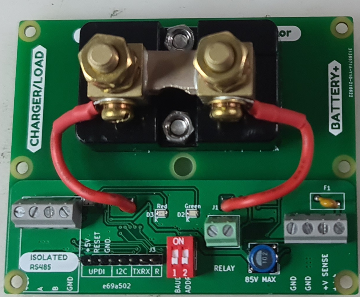
I don’t think that I really explained the connections very well in the video - you need to connect the right hand screw block to the battery (up to 85V).
You can use either of the “GND” terminals to connect to negative, and then you connect BOTH +V sense and +V (which you can’t see as the hole has cut it off!) to the battery positive.
If you are running a long cable from the battery to the shunt to these screw terminals, consider an inline fuse near the battery side.
Once powered up, you can use a multimeter to check the UPDI pins between +5V and GND for a steady 5V.
I was thinking of using low tolerance resistors to make a voltage divider (50% divider for example) to feed the VBUS input of the INA228 and consequently assume that the main outputs of this IC are affected by the same factor as the voltage divider.
that is right but inaccurate. As a certain pack voltage will lead to a certain amount of current flowing through the voltage divider. As the pack voltage is significant lower when your pack is at low charge then at full charge the current flowing through the divider will also change resulting in faulty voltage at the input of the ina228
I would recommend just buying a suitable current shunt, rather than trying to use a device outside the manufacturer specifications.
in the case of having a battery over 85v is it possible to conect the positive to a middle point of the battery pack and having the code get the total voltage reading from the modules for watt calculation? Amps would be the same…
My inverter has a stock 0,3755 mOhm shunt it’s very close to the 150A shunt that you recomend( 0.00033ohm).
Not really, you need the right tool for the job.
hi Stuart, what do you think about this rs485 200v shunt would that be good for the high voltage folk (and everyone else)? Cheap too.
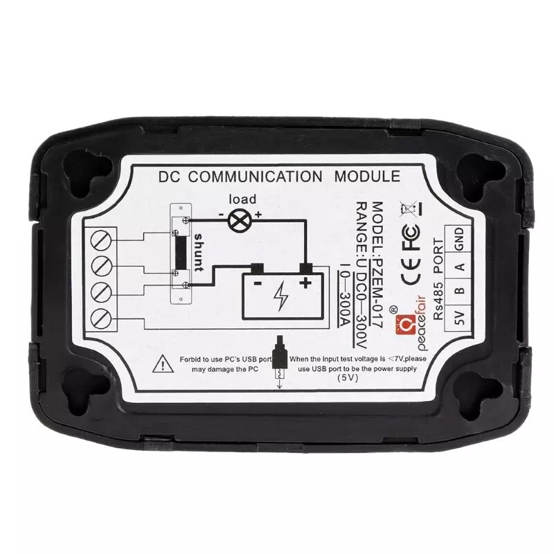
You have to worry when the device says it will damage your PC if you plug it in!
Shows its not electrically isolated from the signals it’s measuring.
in the manual it is supposed to be isolated
the warning is to not power the unit with the pc (mini usb) when under 7v on the battery,
comunication port is passive and optoisolated.
I read that as just the opposite. i.e. use the PC’s USB port if the voltage is <7V.
Even though the maual does say when the test voltage is <7V, please use the independent power supply mode.
The manual also says the instrument is capable of reading frequency, but the register address table says otherwise. Why would a module that reads DC need a frequency function anyway?!
Seems to make more sense grouping the words on the left side of the USB connector symbol together
as well as grouping the words on the right side of said symbol together.
Reading them as one long string from left to right as Forbid to use PC’s USB port When the input test voltage is <7V please may damage the PC use USB port to be the power supply (5V) doesn’t quite read right.
That said, with things made in China, it’s definitely a WTH?! moment when it comes to figuring out
their broken English and datasheets/instructions. Seems like there’s always something lost in the translation.
Surely that - or a similar unit - has been looked at before here? IIRC, our much respected contributor dBC had an input.
[Edit]
It was the PZEM-016: PZEM-016 single phase modbus energy meter - #4 by Bill.Thomson
sry i meant to say never use a pc to power the pzem on the usb port, only a power supply.
the pzem needs external power if main battery is under 7v.
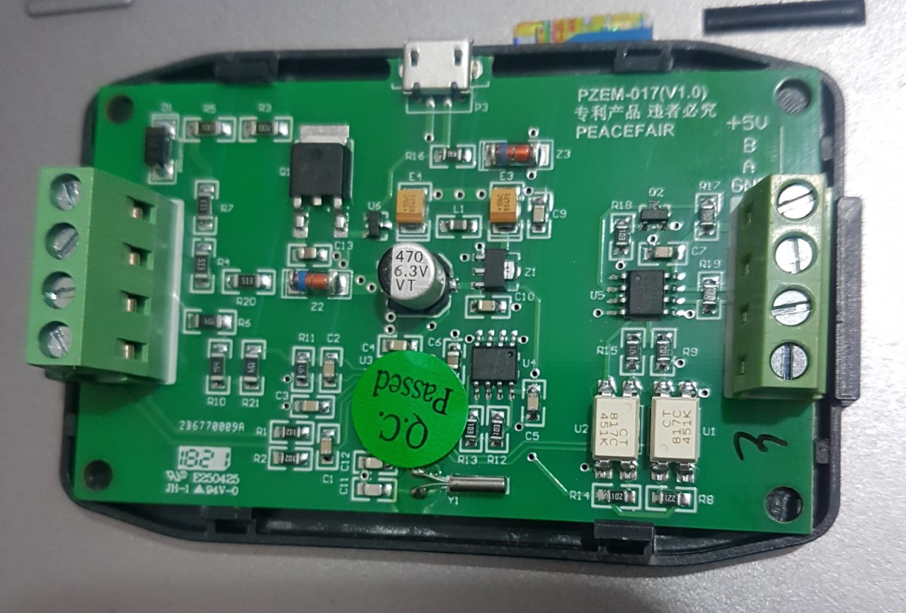
It looks like the rs485 output has two optoisolators on it, which is good.
The code/intelligence if the existing diybms shunt is all contained on the board, it does all the amp hour counting and soc calculations.
This and similar shunts seem to be dumb in that they need an external controller to do that work.
could be a job for the watchdog?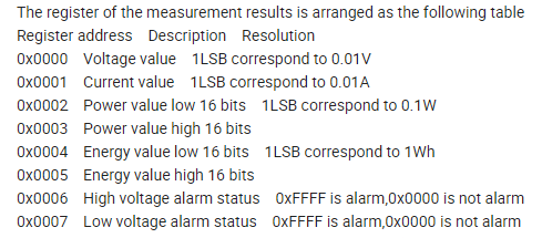
I’ve ordered one from Aliexpress to have a play with, at its most basic, it should be possible to read the power, current and voltage from it.
It uses 9600 baud which is a bit slow for RS485, so that will limit the amount of readings you could ever read from it.
1 Like
This looks very interesting! I just ordered one to play with!
Yeah it’s a bummer that it doesn’t report Ah’s!! I guess if one could poll fast enough you could calculate the amp hours and determine SOC… But, like you said, that needs a controller…
hello stuart
The INA228 component is no longer available from JLCPCB and LCSC. Is there an alternative that I can use?
Hi Andy,
Where are you located?