I tried the same a while ago, but ESPhome does not support the INA228.
It supports the INA226 to my knowladge, but the interfaces/ registers are different.
/Chris
I tried the same a while ago, but ESPhome does not support the INA228.
It supports the INA226 to my knowladge, but the interfaces/ registers are different.
/Chris
Its a slave - it waits for requests (modbus protocol) before sending any data.
The pins on the board allow you to select between modbus addresses.
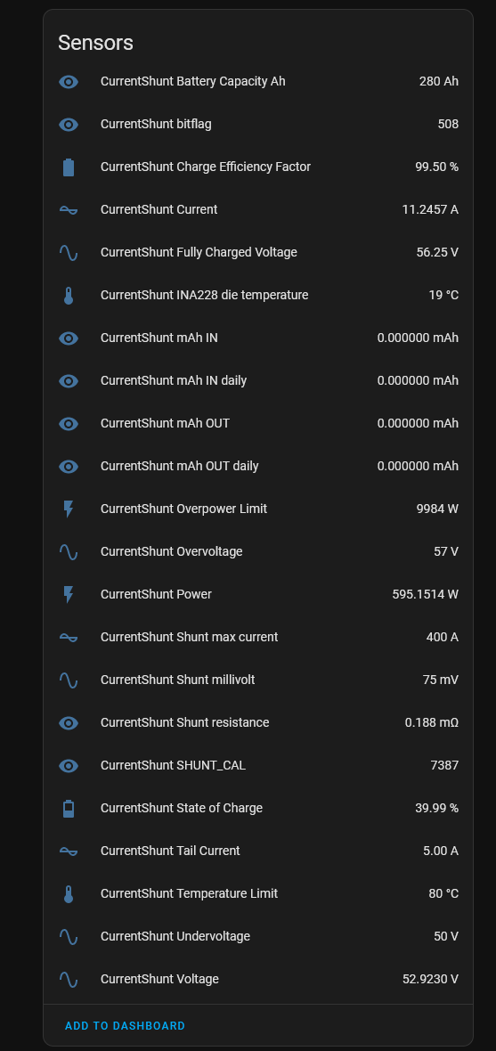
Hi Stuart, I made your current shunt working like a standalone device, but struggling to get mAh IN/OUT values. All other seems to be fine. Below are HA sensors, any suggestions? Thanks!
  - platform: modbus_controller
    name: "CurrentShunt mAh OUT"
    id: cs_mah_out
    address: 4
    register_type: holding
    value_type: FP32_R
    accuracy_decimals: 4
    unit_of_measurement: mAh

  - platform: modbus_controller
    name: "CurrentShunt mAh IN"
    id: cs_mah_in
    address: 6
    register_type: holding
    value_type: FP32_R
    accuracy_decimals: 4
    unit_of_measurement: mAh
accuracy_decimals: 4
Its not a floating point number - its an integer.
Thanks, now it’s ok. U_DWORD was the right type.
  - platform: modbus_controller
    name: "CurrentShunt mAh IN"
    id: cs_mah_in
    address: 6
    register_type: holding
    value_type: U_DWORD
    accuracy_decimals: 0
    unit_of_measurement: mAh
Great - thats a neat solution, shows the power of using common open source standards like MODBUS
Will share that once completed. Only drawback is the LM5009A with 125 mA output, otherwise I’d be able to create “hat” which fits to the uPDI/Debug connector and can be powered from a CurrentShunt itself. Even the 3300uF cap wasn’t enough to provide some juice for ESP32-C3. I’m thinking about LM5007MMX which is pin compatible and provides 500mA.
Btw, I’m getting Power as always positive value, using FP32_R: 32 bit IEEE 754 floating point - same as FP32 but low word first, while Current is correctly positive during charge and negative during discharge. Any hint?
EDIT: temporary hack
  - platform: modbus_controller
    name: "CurrentShunt Power"
    address: 10
    register_type: holding
    value_type: FP32_R
    accuracy_decimals: 4
    unit_of_measurement: W
    device_class: power
    lambda: "if (id(currentshunt_current).state < 0) { return -x; } else { return x; }"
From memory, power is always a positive value, you can obviously calculate this yourself (volt * current) if needed.
Hello @taHC81
How did you go with your work on this?
Hello @pka, yes, fully integrated within Home assistant - including complete configuration. Was a fight!
Good to hear you had success Tomáš
You mentioned sharing something in a previous post - was this a reference to your HA code and, if so did you make it available somewhere? Only reason for asking is because am hoping to get some insights into how to approach communications with standalone shunt…
Thanks for sharing your work Tomáš !
Ďakujem
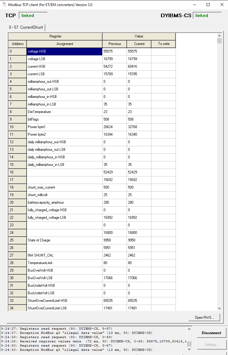
I have a question about the calibration value. according to this calculation:
500A/50mV shunt =   full_scale_current= 500.00A / 50.00 * 40.96 = 409.60 AMPS
                    RSHUNT = (50 / 1000) / 500 = 0.0001
                    CURRENT_LSB = 409.60 / 524288 = 0.00078125
                    R_SHUNT_CAL = 52428800000 * 0.00078125 *  0.0001 = 4096
I get for my shunt 300A/50mV a value of 4095
But in the current shunt setup I get a automaticly calculated value of 4925
Something wrong here or the calculation change?
I ask, because the readings seems to be wrong…
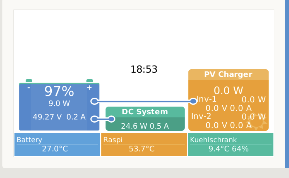
At the screenshots you can see, the 0 load point is not correct, it is around 34W too little. (DC System is a Victron Smart shunt in series). in 24 hours with loading and unload there is a difference of about 800W.