Thanks very much, i just checked. it seems right. so there is still light on the dark ![]() Lets wait until May!!
Lets wait until May!!
I just built the INA229 add on board, I have a few spares available in Belgium if someone is interested.
Shunt voltage was first showing 0, had to reflow/solder until it worked.
The bank voltage an shunt voltage is somewhat off, which value is passed to the Victron GX?
The shunt voltage is the most correct one.
Il try to recalibrate the modules again.
If a shunt is fitted, that voltage and current measurement is used for CANBUS communication with PylonTech/Victron.
OK, now also TI eliminated the Time on there website for the INA228. ![]()
Dang, you could search octopart and pay 5x the cost for the chance of a part being available (though I don’t recommend that, don’t support scalpers!)

Mouser write me: I send INA228 22.5. 2023 …
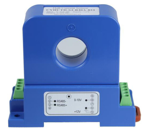
is it possible to add support of such Hall Effect current sensors? the RS-485 protocol of them is pretty detailed described…
@stuart is it possible to integrate this type of sensor in the poste above?
Hi,
Does anyone have extra PCB for Current Monitor willing to sell/send?
Thx
Bare pcb or fully assembled?
Hi,
Bare, or semi-bare is sufficient ![]()
Thx
This could be integrated - would need additional code written etc. It only supports current monitoring, so you wouldn’t get amp-hour counting or state of charge etc. Which in my opinion are critical to these sort of devices.
@stuart I am about to pull the trigger on the ordering some v4.6 controllers, I have some questions
Is there a new video on how the new controller now connects to Shunt ?
Is there a new shunt board to support the v4.6 controller ?
If it’s the existing shunt board, what components do we still need to mount to the shunt board
And lastly can we use any shunt with 75mV ?
Thanks, in advance
Not required - the shunt circuit is on the controller board - theres a 4 pin header on the top of the board to connect the shunt to.
i need one
thanks alot mate.
i was sitting on this… for 3 days. also works great with arduino uno
Hello, I’m trying to bring this Shunt to life, but having no data on TX/RX pins. Not connected anything on RS485 yet… Does it need register read in order to get some reply, or is it broadcasting data?
In case it requires active RS485 communication, which are the addresses configurable with DIP switch? Same for baud rate. Haven’t found this info anywhere. Thanks!
EDIT: I’ve found baudrate 19200/9600 and modbus address 90/98…
This is what I see on I2C with logic analyzer:
Time [s],Packet ID,Address,Data,Read/Write,ACK/NAK
1.755737875000000,0,@ (0x40),'5' (0x05),Write,ACK
1.755808875000000,1,@ (0x40),'18' (0x12),Read,ACK
1.755839250000000,1,@ (0x40),'190' (0xBE),Read,ACK
1.755869000000000,1,@ (0x40),P (0x50),Read,NAK
1.756303750000000,2,@ (0x40),'7' (0x07),Write,ACK
1.756374875000000,3,@ (0x40),'255' (0xFF),Read,ACK
1.756405125000000,3,@ (0x40),'253' (0xFD),Read,ACK
1.756434875000000,3,@ (0x40),P (0x50),Read,NAK
1.756641625000000,4,@ (0x40),\n (0x0A),Write,ACK
1.756712625000000,5,@ (0x40),'255' (0xFF),Read,ACK
1.756742875000000,5,@ (0x40),'255' (0xFF),Read,ACK
1.756772625000000,5,@ (0x40),'254' (0xFE),Read,ACK
1.756802375000000,5,@ (0x40),'217' (0xD9),Read,ACK
1.756832000000000,5,@ (0x40),d (0x64),Read,NAK
3.763627250000000,6,@ (0x40),'5' (0x05),Write,ACK
3.763698375000000,7,@ (0x40),'18' (0x12),Read,ACK
3.763728625000000,7,@ (0x40),'190' (0xBE),Read,ACK
3.763758375000000,7,@ (0x40),P (0x50),Read,NAK
3.764193125000000,8,@ (0x40),'7' (0x07),Write,ACK
3.764264125000000,9,@ (0x40),'255' (0xFF),Read,ACK
3.764294500000000,9,@ (0x40),'253' (0xFD),Read,ACK
3.764324125000000,9,@ (0x40),@ (0x40),Read,NAK
3.764521250000000,10,@ (0x40),\n (0x0A),Write,ACK
3.764592375000000,11,@ (0x40),'255' (0xFF),Read,ACK
3.764622625000000,11,@ (0x40),'255' (0xFF),Read,ACK
3.764652375000000,11,@ (0x40),'254' (0xFE),Read,ACK
3.764682000000000,11,@ (0x40),'217' (0xD9),Read,ACK
3.764711750000000,11,@ (0x40),'14' (0x0E),Read,NAK
5.771541250000000,12,@ (0x40),'5' (0x05),Write,ACK
5.771612375000000,13,@ (0x40),'18' (0x12),Read,ACK
5.771642750000000,13,@ (0x40),'190' (0xBE),Read,ACK
5.771672375000000,13,@ (0x40),` (0x60),Read,NAK
5.772107250000000,14,@ (0x40),'7' (0x07),Write,ACK
5.772178375000000,15,@ (0x40),'255' (0xFF),Read,ACK
5.772208625000000,15,@ (0x40),'253' (0xFD),Read,ACK
5.772238375000000,15,@ (0x40),0 (0x30),Read,NAK
5.772438750000000,16,@ (0x40),\n (0x0A),Write,ACK
5.772509750000000,17,@ (0x40),'255' (0xFF),Read,ACK
5.772540000000000,17,@ (0x40),'255' (0xFF),Read,ACK
5.772569750000000,17,@ (0x40),'254' (0xFE),Read,ACK
5.772599500000000,17,@ (0x40),'216' (0xD8),Read,ACK
5.772629250000000,17,@ (0x40),'182' (0xB6),Read,NAK
7.780502125000000,18,@ (0x40),'5' (0x05),Write,ACK
7.780573250000000,19,@ (0x40),'18' (0x12),Read,ACK
7.780603500000000,19,@ (0x40),'190' (0xBE),Read,ACK
7.780633250000000,19,@ (0x40),P (0x50),Read,NAK
7.781068000000000,20,@ (0x40),'7' (0x07),Write,ACK
7.781139125000000,21,@ (0x40),'255' (0xFF),Read,ACK
7.781169375000000,21,@ (0x40),'253' (0xFD),Read,ACK
7.781199125000000,21,@ (0x40),` (0x60),Read,NAK
7.781405875000000,22,@ (0x40),\n (0x0A),Write,ACK
7.781476875000000,23,@ (0x40),'255' (0xFF),Read,ACK
7.781507250000000,23,@ (0x40),'255' (0xFF),Read,ACK
Hi @taHC81
thats the informations you are looking for?

Here are the registers: https://github.com/stuartpittaway/diyBMS-CurrentShunt/blob/master/Code/diybmsCurrentShunt/MODBUS%20Registers.md
/Chris
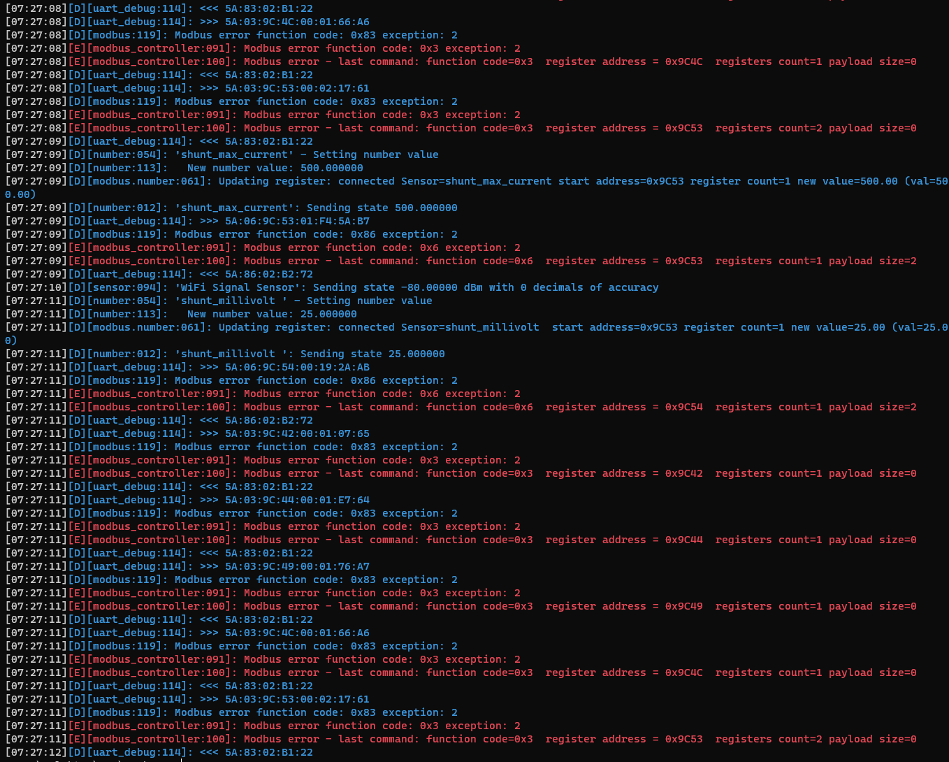
No Chris, I’m trying to use Current shunt as a standalone device, but struggling to get it working. Now I’m trying to interface it via RX & RX pins and ESPhome node. Still getting exceptions about ILLEGAL DATA ADDRESS. I do understand I have to send shunt parameters first to make it running… Getting 1 short red LED blink every 2 seconds and 3 green LED blinks with very short delay.