This is probably a simple question so I’m putting it under ‘Getting Started’ even though I’ve had my EmonTX-v3’s for quite some time.
I’m actually trying to make sense of the data for the first time since I first installed all this stuff and got it running. I have qty 3 EmonTX3’s with radios, CT’s all bought from OEM shop. Wall Warts are a Digikey unit that we deemed to be sufficient in another one of my posts. (“TDC Power DA-10-09”)
So I have the high current CT’s connected to my Mains L1/L2 (north america, split phase 240) and some of the lower current CT’s connected to various circuits, including my electric hot water heater (just L1) and my Air Conditioner (L1 and L2).
First things first. My Air Conditioner, a 2.5ton unit, is reporting approximately 650-700W per leg which is approximately 5.5A @ 240V. A clamp meter on the same legs at the same time, is reporting 6.7A. That seems outside of the ‘error range’ for either device.
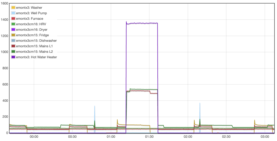
Second, my Hot Water Heater is showing 1359W per leg, but my Mains L1/L2 are each reporting 550W. I’ve either discovered a magical source of free energy, or there is something wrong. Before I start writing the patent, I figured I’d try to see where the disparity is.
This one is relatively easy. Power Factor.
You can’t equate real power, which is what the emonTx calculates, to a current and a voltage. You can read the sordid details in 'Docs → Learn → Electricity Monitoring`, but it boils down to an inductive load like the compressor on your Air Conditioner draws more current that it ought for the power it dissipates. If your sketch in the said emonTx V3 is recent enough, you should be able to get it to print the currents to the serial output - they’re not normally sent by radio but they could be by editing and reloading the sketch.
Doing the numbers for you, 6.7 A @ 120 V = 804 VA (Volt Amperes, NOT watts), so the power factor of that load is about 0.84, which is wholly credible for a 700 W or so induction motor.
There’s something fundamentally wrong here. Is this connected across 240 V? are you sure you’re measuring the correct current and voltage? What maths are you doing (in emonCMS?) to get to 1359W per leg?
I guess power factor makes sense. I hadn’t considered that. Thanks.
As for the 1395, in the screenshot above, the purple line just below 1400 is my hot water heater. The green and red lines at 550ish are my incoming power from the grid. The HWH is 240VAC and I have a CT on only one of the two wires going to the double-breaker.
What about emonCMS? I’m confused by what you mean by “per leg”.
As it’s a resistive load, I would expect the power delivered to the heater would be 2 × current (A) × voltage (nominally 120 V), so emonCMS should take the power the emonTx reports - which is calculated using the voltage of one leg to neutral - and double it.
Another way of looking at it is, you can connect the centre point of the heating element to the neutral, and nothing changes because no current flows because the voltage at the centre is zero. Therefore, you can cut the element into two equal parts, and then you have two elements, each one measured correctly by the emonTx because each is is running at 120 V.
The real question is, because 550 W × 2 is rather too much less than 1359 W, are the two c.t’s on the service entrance wires accurate, and properly calibrated, and likewise the single c.t. on the water heater? The discrepancy is about 24%, far too much to be a single component tolerance, and probably too much for many all adding up the wrong way.
What are the “high current CTs”? If they are not SCT-013-000s, was it necessary to change the calibration and did you do so? What prompts me to ask is the steps at 01:05 and 01:30 when the fridge goes on and off should be the same height on the SEW trace, and they aren’t.
If you think the calibration is correct, then if it’s easy and safe to do, is it possible to move one of the c.t’s onto the same place as one of the others, to get a direct comparison so that you can compare the accuracy - either one (or both) SEW CTs onto the water heater feed, or the water heater feed c.t. onto one of the SEWs?
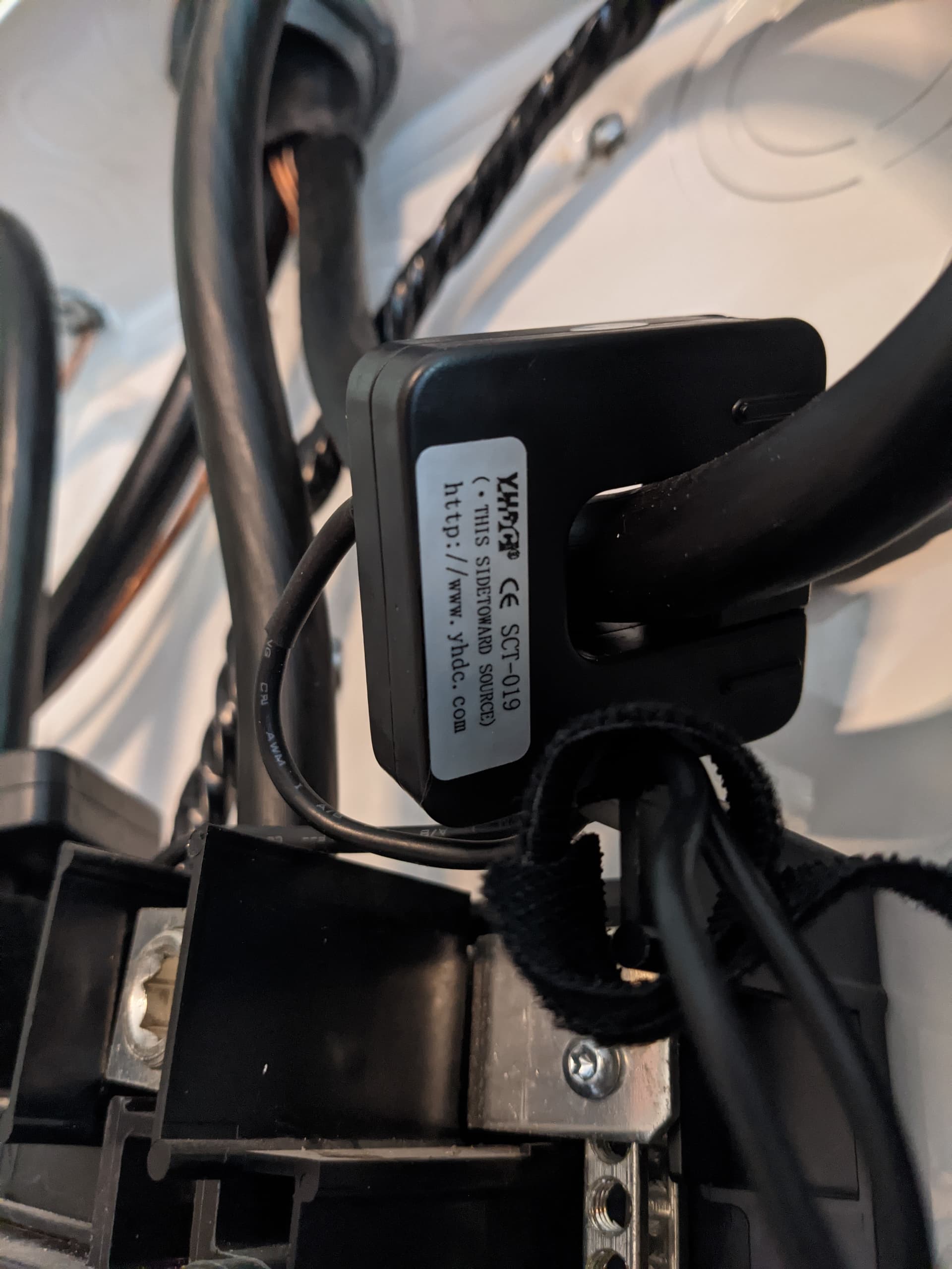
The CT’s on my Mains are the ones that came from the OEM shop when I bought my EmonTXv3’s. I pulled the cover off my service entrance panel and snapped a photo.
The rated current is 200 A, and the output at this current is 33 mA. For the SCT-013-000 which the emonTx is calibrated for, the same numbers are 100 A & 50 mA .
So you are reading 66 / 100 of what you should on your two SEWs. The ‘proper’ way to do this is to calibrate those inputs in your emonTx, i.e. change the calibration constant from 90.9 to 137.72 or if you can’t do this, you can ‘fiddle’ the calibration by changing the appropriate number in the scales = line in emonhub.conf from 1.0 to 1.515, or multiply by 1.515 somewhere in the input processing. This should make your 550 W more like 833 W and twice this is 1666 W leaving about 300 W for the other appliances, which looks a lot closer.
Ideally, you should also set the phase error calibration [zz.z] which you’ll have to adjust by trial and error: with only your water heater and possibly your furnace running (i.e. nothing else if possible, especially things like the aircon and fridge with motors in them) adjust this so that the power factor is as close to 1.0 as possible. I can’t even guess a number because I’ve never tested one of those c.t’s with your a.c. adapter (and it’s the combination of errors of the two that you’re correcting for).
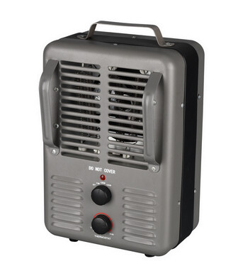
The furnace will have an air handler motor, so not the best load to use for calibration.
It’s not likely a large motor. Typically they’re 1/3 or 1/2 hp devices.
We don’t have an item we call “furnace” in UK homes, so I didn’t have a clear idea of what it was - hence the inclusion of the word “possibly”.
It’s a matter of judging whether the higher current that the additional load gives will match the inaccuracy that the reactive component adds. A small motor like that will have a very poor power factor, maybe less than 0.5, but the overall effect of this can only be known when full details are available.
Yep, we use a number of names.
Some folks simply call them heaters, others use the term space heat or forced air heat,
and yet others refer to them as central heat
Reminds me of a bit of humor from George Carlin…
He remarked “Hot water heater. Let’s see, if the water’s already hot, why are we heating it?”
A lot happened here while I was working in the garage yesterday.
There was a long period of time when I wasn’t recording anything because my pi suffered from an SD card failure and I was pre-occupied with a frantic work schedule. Once I ‘retired’, I started tackling my lengthy TODO list. I built an Emoncms instance on my Proxmox server and relegated another Pi to submitting data to it. Not much gets done keyboard-wise during the summer. I have a forest to manage, lots of outdoor projects, etc. Whatever gets done is in the hour or two after I wake up and before breakfast.
So yeah, our ‘furnace’ is basically a natural gas burner and blower motor. Ours has an ECM motor but is still AC.
When I think of a Herman-Nelson heater, I think of something on a trailer blowing hot air under a big insulated tarp tied over an airplane in Canada’s north where -55C is not uncommon.
Anyway, I haven’t resolved my problem but at least now I understand it. Calibrating the phase error will be a bit of an undertaking. I can turn off my fridge, deep freeze, furnace, etc. I wonder how much our induction range contributes to phase error, though it’s used relatively infrequently.
Another part of the problem is that the house only apparently accounts for part of our overall energy usage. Our power splits at the pole on the side of our driveway. One feed goes to the house, the other feed goes to the shop and my office (the Bunker). I’d have to order an EmonTX4 I guess.
Thanks for the amazing help, though. There’s a lot of reading in the docs.
I don’t think so - a few minutes if your emonTx V3’s software can show the power factor when asked via the serial output – c1 to turn it on, c0 to turn it off. You only need to turn those appliances with motors or electronic power supplies off for 5 minutes or so while you do it.
So not, not the ‘furnace’ which is basically the blower motor.
I’m assuming if I connect to the Mini-USB connector on the EmonTX3, I will see an ACM or CDC device appear on my host (a Mac in this case). Because nothing new appears. So it’s either a cable problem or I have to do something to the EmonTX3 to get the serial? Or do I have to upload the direct serial sketch?
The serial interface is on the FTDI connector, the 6-pin header on the opposite edge to the jack sockets. You need a programmer, like you did in post no.7 (or is that where you are?), either to change the configuration or indeed to upload a new sketch.
Finally got an FTDI hooked up and confirmed I can set the CT cal but I don’t think ‘c1’ is working. I presume my EmonlibCM is too old.
emonTx V3.4 EmonLibCM Continuous Monitoring V1.20
So do I understand correctly I need to get this emontxv3+ftdi cable plugged into the Pi running emonhub.py? Or do I need to get it to my ProxMox server running emoncms and then forward the applicable ttyUSB to the applicable container? Or I can run PlatformIO? Or I can install the Arduino IDE, compile the sketch and program it? I don’t need to get an ISP and run avrdude and set fuses, etc?
This is all complicated by the fact that I have all this stuff spread all over hells half acre and this EmonTXv3 is in an awkward place.
You only need to adjust the phase calibration for the emontx V3, correct?
How easy is it to take it to the bench, with the c.t.(s) and the a.c. adapter, find a decent resistive load (electic kettle?) and temporarily set it up there? I’d use the Arduino IDE (because I have it on here) but any 2-way serial software should allow you to communicate.
It’s the sketch that implements the configuration commands - the code to extract the values has always been part of emonLibCM.