CT accuracy - odd looking graph

The instructions I saw said to type "c1 into the serial monitor on the emontxv3 but the command didn’t seem to produce any new output. The “k” calibration command did work as well as saving to eeprom. So I figured I had an old version of the firmware that doesn’t support the “c” command. Hence my firmware update question.

Moving the whole kit and caboodle into the lab is of course doable. I just have to gather up enough inertia.

It appears that I released a sketch with the c command in June 2020, which reports itself as “emonTx V3.4 + RFM69CW EmonLibCM Continuous Monitoring V0.1”

But I also have a version labelled “Trystans”, which doesn’t have the c command – so it looks as if in his wisdom he removed it, or he started from a different base; and this is what you might have.

Well, I think since I placed my order in 2019, I’m pretty sure that explains the lack of a ‘c’ command. :slight_smile:

So I’ll just upgrade the firmware first. Things happen slowly around here.

I figured I better start with upgrading the firmware on the emontxv3 following the instructions here: https://github.com/openenergymonitor/emontx3/tree/master/firmware/emonTx34/emonTx34_CM

It appeared to upgrade successfully and now I see:

emonTx V3.4 Continuous Monitoring V2.4.0
OpenEnergyMonitor.org
No EEPROM config
Settings:
Band 433 MHz, Group 210, Node 15, 7 dBm
Calibration:
vCal = 268.97
assumedV = 240.00
i1Cal = 90.90
i1Lead = 3.00
i2Cal = 90.90
i2Lead = 3.00
i3Cal = 90.90
i3Lead = 3.00
i4Cal = 16.67
i4Lead = 6.00
datalog = 9.85
pulses = 1
pulse period = 100
RF on
temp_enable = 1
JSON Format Off
RFM69CW  Freq: 433MHz Group: 210 Node: 15 
USA Vcal active: 130.00
Factory Test
CT1 detected, i1Cal:90.90
CT2 detected, i2Cal:90.90
CT3 detected, i3Cal:90.90
CT4 detected, i4Cal:16.67
Temperature Sensors found = 0 of 3
Temperature measurement is enabled.

AC present - Real Power calc enabled
MSG:1,Vrms:114.08,P1:181,P2:69,P3:32,P4:4,E1:32907,E2:23693,E3:1928,E4:4847,pulse:0

Unfortunately, the calibration I updated in CT1/CT2 has reverted so presumably the E^2 has been reset to default.

Also, unfortunately, the firmware no longer accepts input from the serial port. I’ve confirmed my FTDI dongle and terminal program are working by shorting the tx/rx pins and loopback is working.

Thus, I can’t re-calibrate CT1/CT2, nor do anything else.

and yes, I’ve experimented with 8n1, 7e1, cr, cr/nl, nl, etc. Disabled hw flow control in the terminal. etc. I’m pretty sure the uart on the 328 is fine given I was able to update the firmware through it. Looking through the source, I’ve tried as many combinations of +++\r\n, ++s\r\n, etc.

Thoughts?

Are you using the Arduino IDE, or something different? It has always worked for me with the Arduino IDE (under Linux).

You don’t of course TYPE \r\n, your terminal program should those characters [cr] and [lf] automatically or semi-automatically when you hit [Enter] or whatever.

All is not lost. If you can’t configure/calibrate it on-line, then edit the source file, compile and upload it with the constants changed to suit. This is how we did it before we developed the on-line configuration.

haha yes, I’m specifically using ctrl-j and ctrl-m, and in minicom I’ve also set cr/nl.

I’ve tried ‘screen’, ‘miniterm.py’, ‘platformio device monitor’ and ‘minicom’.

‘minicom’ is what I use on a day to day basis with other devices and is what I’m most familiar with.

Just for humor value, I just tried the Arduino IDE and it also is not able send data to the device.

I also just re-flashed using ‘pio run -t upload’ and it was successful, confirming that the hardware is fine.

Given that serial loopback works, and emontxv3 is sending me messages successfully, it’d be hard to convince me the problem is the terminal program.

Anyway, I hacked the calibration into the code as you suggested and I’m back to where I was before. Still don’t know my phase error but I think I’m out of mental bandwidth on this.

All you can do is set up a purely resistive load and try various values and observe the effect. You’re aiming for a power factor as close to 1.0 as possible, but the peak is ill-defined and quite broad. Don’t start with large changes until you’ve found out which side of the peak you’re on. Unfortunately, this is a lot easier if you can adjust the values without recompiling, but you could - if you wish - modify the sketch to step through a range of values with each report, and hope you choose a wide enough range and small enough steps to be able see a ‘best’ angle to set.

This is concerning. It seems to suggest it is the [cr][lf] combination that’s tripping you up. Could it be your Mac is sending [lf][cr], or [cr][cr][lf], or something like this?

I’ve loaded the Jeelib Classic version of your sketch and I can communicate as expected with the Arduino IDE. However, I cannot get the sketch to respond using Minicom, even though I can see the output as normal.

At the place I worked about 30 years ago, I had a RS232 ‘data sniffer’ - and it was invaluable for solving this sort of problem - clip it onto the Tx & Rx lines and watch the data flowing past in each direction.

Short of writing a sketch to echo back the data it’s receiving, which might show if something really weird is happening, I can’t figure out what your problem is. This is my best suggestion now, but I’m fairly certain I won’t have the time to do anything for many days.

I have a logic analyzer, and all manner of test equipment in my lab. I just have to relocate the emontxv3 and dig into it. I may have some bandwidth later this week.

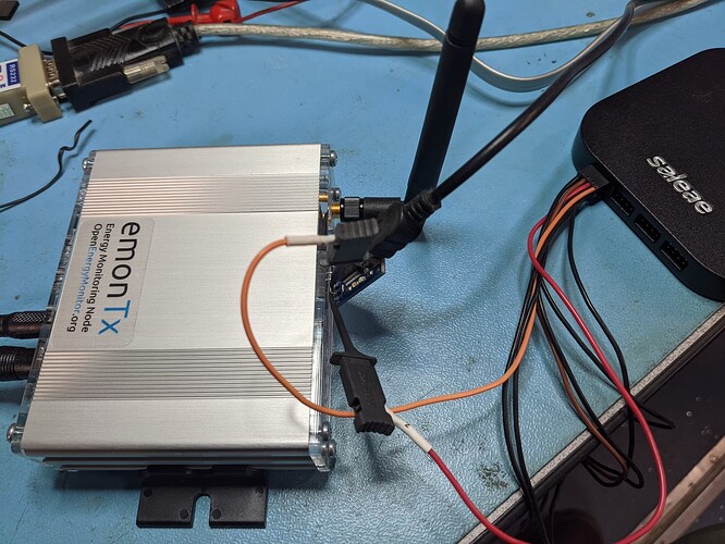
Ok. I moved my emontxv3 into the lab and connected my logic analyzer.

The code definitely does not respond to “\r\n”. It does however respond to “\n”:

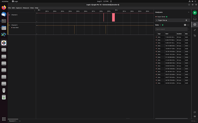
You can see the bottom channel (3) are the keystrokes I’m sending to the emontxv3. The data listing on the right shows that I sent a 0x6c (‘l’) at 40.471s, and then a 0x0a (‘^J’) at 40.877 and you can subsequently see on channel 2 that I got a ‘blob’ of settings info just before 41s.

You can see I attempted l\r\n a number of times, as well as l\n\r. I also tried l\r which of course didn’t work.

Anyway, that’s the smoking gun right there.

Armed with that information, I was able to do “c1\n” and it’s now spewing more data:

MSG:84,Vrms:240.00,pulse:0,I1:0.000,I2:0.000,I3:0.000,I4:0.000,pf1:0.0000,pf2:0.0000,pf3:0.0000,pf4:0.0000
MSG:85,Vrms:240.00,pulse:0,I1:0.000,I2:0.000,I3:0.000,I4:0.000,pf1:0.0000,pf2:0.0000,pf3:0.0000,pf4:0.0000
MSG:86,Vrms:240.00,pulse:0,I1:0.000,I2:0.000,I3:0.000,I4:0.000,pf1:0.0000,pf2:0.0000,pf3:0.0000,pf4:0.0000
MSG:87,Vrms:240.00,pulse:0,I1:0.000,I2:0.000,I3:0.000,I4:0.000,pf1:0.0000,pf2:0.0000,pf3:0.0000,pf4:0.0000
MSG:88,Vrms:240.00,pulse:0,I1:0.000,I2:0.000,I3:0.000,I4:0.000,pf1:0.0000,pf2:0.0000,pf3:0.0000,pf4:0.0000

I’ll go grab a CT later and some sort of resistic load like a direct plug-in soldering iron maybe. If I steal my wife’s kettle and bring it into the lab, it won’t be allowed back in the house. :laughing:

There’s definitely something novel happening there - I’ve only ever touched a Mac once, and this was many years ago, so I know almost nothing about what might be going on. What I can’t understand is we have a few Mac users, and as far as I can recollect, this is the first time someone has encountered a problem (or at least reported it).

Ideally, you want a current similar to your “normal” current - whatever this might be because the phase error of a c.t. does vary with current, and it’s generally a “bathtub” shape. It tends to be lowest over the normal working range, rising dramatically at low and high currents. You can always use a multi-turn primary winding for your c.t. to give it more ampere-turns. I use a 250 W (~1 A) convector heater and 20 turns, so 20 At and the c.t. thinks it has 20 A flowing.

I should have mentioned, in the lab I’m on a Linux machine. Anyway, it doesn’t matter at this point what’s at the other end of the serial port. The Logic analyzer is reporting what bits are arriving at the RX pin on the emontxv3 and what bits are coming out the TX pin on the emontxv3.

Anyway, I’m passed that now.

Seemingly no matter what I set the calibration to, pf1 doesn’t change. I’m using a 1500w baseboard heater with no fan (it is purely resistive).

MSG:454,Vrms:109.54,pulse:0,I1:3.695,I2:0.000,I3:0.000,I4:0.000,pf1:-0.9979,pf2:0.0000,pf3:0.0000,pf4:0.0000
MSG:455,Vrms:109.53,pulse:0,I1:3.692,I2:0.000,I3:0.000,I4:0.000,pf1:-0.9979,pf2:0.0000,pf3:0.0000,pf4:0.0000
MSG:456,Vrms:109.53,pulse:0,I1:3.691,I2:0.000,I3:0.000,I4:0.000,pf1:-0.9979,pf2:0.0000,pf3:0.0000,pf4:0.0000
Cal: k1 137.72 1.00
MSG:457,Vrms:109.52,pulse:0,I1:3.690,I2:0.000,I3:0.000,I4:0.000,pf1:-0.9979,pf2:0.0000,pf3:0.0000,pf4:0.0000
Cal: k1 137.72 5.00
MSG:458,Vrms:109.53,pulse:0,I1:3.690,I2:0.000,I3:0.000,I4:0.000,pf1:-0.9979,pf2:0.0000,pf3:0.0000,pf4:0.0000
MSG:459,Vrms:109.48,pulse:0,I1:3.688,I2:0.000,I3:0.000,I4:0.000,pf1:-0.9979,pf2:0.0000,pf3:0.0000,pf4:0.0000
MSG:460,Vrms:109.45,pulse:0,I1:3.688,I2:0.000,I3:0.000,I4:0.000,pf1:-0.9979,pf2:0.0000,pf3:0.0000,pf4:0.0000
Cal: k1 137.72 -2.00
MSG:461,Vrms:109.38,pulse:0,I1:3.680,I2:0.000,I3:0.000,I4:0.000,pf1:-0.9979,pf2:0.0000,pf3:0.0000,pf4:0.0000
MSG:462,Vrms:109.34,pulse:0,I1:3.680,I2:0.000,I3:0.000,I4:0.000,pf1:-0.9979,pf2:0.0000,pf3:0.0000,pf4:0.0000
MSG:463,Vrms:109.44,pulse:0,I1:3.682,I2:0.000,I3:0.000,I4:0.000,pf1:-0.9979,pf2:0.0000,pf3:0.0000,pf4:0.0000
MSG:464,Vrms:109.49,pulse:0,I1:3.681,I2:0.000,I3:0.000,I4:0.000,pf1:-0.9979,pf2:0.0000,pf3:0.0000,pf4:0.0000

Is it because I’m using the high current CT? Or am I just not doing it right?

Edit: I just re-read your message. I’ll get more wire and do a bunch more turns.

0.9979 isn’t too bad - it represents an error of 3.7°. Generally speaking, the better the c.t, the smaller and more constant the error will be. But irrespective of current, changing the phase error calibration should change the power factor it reports, and i1Lead = 3.00 should change too to reflect the new value.

after adding about 10 turns (before I ran out of room in the CT), I’m now seeing -.9995

Still nothing changes after playing with a few values.

MSG:155,Vrms:108.05,P1:-3130,E1:48287,pulse:0,I1:28.988,I2:0.000,I3:0.000,I4:0.000,pf1:-0.9994,pf2:0.0000,pf3:0.0000,pf4:0.0000
MSG:156,Vrms:108.09,P1:-3132,E1:48279,pulse:0,I1:29.001,I2:0.000,I3:0.000,I4:0.000,pf1:-0.9995,pf2:0.0000,pf3:0.0000,pf4:0.0000
MSG:157,Vrms:108.06,P1:-3130,E1:48270,pulse:0,I1:28.989,I2:0.000,I3:0.000,I4:0.000,pf1:-0.9994,pf2:0.0000,pf3:0.0000,pf4:0.0000
Cal: k1 137.72 1.90
MSG:158,Vrms:108.08,P1:-3130,E1:48262,pulse:0,I1:28.987,I2:0.000,I3:0.000,I4:0.000,pf1:-0.9995,pf2:0.0000,pf3:0.0000,pf4:0.0000
MSG:159,Vrms:108.13,P1:-3132,E1:48253,pulse:0,I1:28.991,I2:0.000,I3:0.000,I4:0.000,pf1:-0.9994,pf2:0.0000,pf3:0.0000,pf4:0.0000
Cal: k1 137.72 0.00
MSG:160,Vrms:108.21,P1:-3134,E1:48244,pulse:0,I1:28.986,I2:0.000,I3:0.000,I4:0.000,pf1:-0.9994,pf2:0.0000,pf3:0.0000,pf4:0.0000
MSG:161,Vrms:108.15,P1:-3131,E1:48236,pulse:0,I1:28.971,I2:0.000,I3:0.000,I4:0.000,pf1:-0.9995,pf2:0.0000,pf3:0.0000,pf4:0.0000
MSG:162,Vrms:108.25,P1:-3137,E1:48227,pulse:0,I1:29.004,I2:0.000,I3:0.000,I4:0.000,pf1:-0.9994,pf2:0.0000,pf3:0.0000,pf4:0.0000
Settings:
Band 433 MHz, Group 210, Node 15, 7 dBm
Calibration:
vCal = 268.97
assumedV = 240.00
i1Cal = 137.72
i1Lead = 0.00
i2Cal = 137.72
i2Lead = 3.00
i3Cal = 90.90
i3Lead = 3.00
i4Cal = 16.67
i4Lead = 6.00
datalog = 9.85
pulses = 1
pulse period = 100
RF on
temp_enable = 1
JSON Format Off
Temperature Sensors found = 0 of 3
Temperature measurement is enabled.

MSG:163,Vrms:108.21,P1:-3133,E1:48219,pulse:0,I1:28.986,I2:0.000,I3:0.000,I4:0.000,pf1:-0.9992,pf2:0.0000,pf3:0.0000,pf4:0.0000
MSG:164,Vrms:108.27,P1:-3138,E1:48210,pulse:0,I1:29.011,I2:0.000,I3:0.000,I4:0.000,pf1:-0.9994,pf2:0.0000,pf3:0.0000,pf4:0.0000
I run under Linux, and I’ve got cr + lf set in the Arduino IDE. It works for me.

I think I’d settle for 0.9995. It represents an error of less than 2°.
(But it also shows the difference current makes - the error has nearly halved.)

But I can’t see why changing the phase error calibration doesn’t affect the power factor. It must be disabled in the sketch. Can you give me an exact link to the sketch you’re using?

I’m using the instructions on this page:

https://docs.openenergymonitor.org/emontx3/firmware.html

I did:

git clone https://github.com/openenergymonitor/emontx3
cd emontx3/firmware/emonTx34/emonTx34_CM
pio run -t upload

and I’m at:

$ git rev-parse HEAD
cf1288d05703651ab2daaddd02bd1601ecdaadea

I just re-confirmed that when I change the calibration value, that ‘i1Lead’ does change:

Settings:
Band 433 MHz, Group 210, Node 15, 7 dBm
Calibration:
vCal = 268.97
assumedV = 240.00
i1Cal = 137.72
i1Lead = 3.00
i2Cal = 137.72
i2Lead = 3.00
i3Cal = 90.90
i3Lead = 3.00
i4Cal = 16.67
i4Lead = 6.00
datalog = 9.85
pulses = 1
pulse period = 100
RF on
temp_enable = 1
JSON Format Off
Temperature Sensors found = 0 of 3
Temperature measurement is enabled.

MSG:8,Vrms:113.64,P1:0,E1:48175,pulse:0,I1:0.036,I2:0.000,I3:0.000,I4:0.000,pf1:0.0067,pf2:0.0000,pf3:0.0000,pf4:0.0000
MSG:9,Vrms:113.60,P1:0,E1:48175,pulse:0,I1:0.036,I2:0.000,I3:0.000,I4:0.000,pf1:0.0105,pf2:0.0000,pf3:0.0000,pf4:0.0000
Cal: k1 137.72 1.00
Settings:
Band 433 MHz, Group 210, Node 15, 7 dBm
Calibration:
vCal = 268.97
assumedV = 240.00
i1Cal = 137.72
i1Lead = 1.00
i2Cal = 137.72
i2Lead = 3.00
i3Cal = 90.90
i3Lead = 3.00
i4Cal = 16.67
i4Lead = 6.00
datalog = 9.85
pulses = 1
pulse period = 100
RF on
temp_enable = 1
JSON Format Off
Temperature Sensors found = 0 of 3
Temperature measurement is enabled.

That means nothing to me. Are you telling me in a convoluted way it’s this one: emonTx34_CM: continuous sampling firmware ? If so, which radio option are you using?

Sorry, I assumed you spoke ‘git’. :slight_smile: So yes, I’m running emonTx34_CM.

I don’t actually know which radio option it built. Presumably whatever the default build is in emonTx34_CM. It doesn’t appear to be in the firmware version string reported by the ‘l’ command.

This is the firmware.hex that it seems to have built/uploaded; in case that helps.

firmware.hex (87.8 KB)

I was just following the instructions on the firmware page. I’m happy to use a different process if you’d like.

ok. So I figured out the source of the “\r\n” vs. “\n” confusion. There’s just a minor bug in the script.

We can see here that the loop just coalesces data into “input” until it sees a linefeed character:

However, we can see here that the ‘l’ command will not work if more than one character has been received… If you send “l\r\n”, then len==2 and thus the ‘l’ command will not work. It will only work if you send “l\n” thus making len==1.

Since I was using ‘l’ to test whether I could talk to the serial port, it wasn’t working for me if I used “\r\n”.

Here’s a quick fix to the \r\n handling. Now I can use ‘l’, and ‘c1’, ‘c0’, etc, without keyboard gymnastics.

I can send a pull request if you want to take it.