Been busy designing a distributed solar pv router. I say distributed because my aim is to measure the flow of energy to and from the grid in the meter box and cater for any number of load switches on a priority basis anywhere in the house and outbuildings. To do this I have used an ESP32 to measure the AC voltage and current with a CT. This unit then signals the status of the Joule buffer using MQTT and also imposes an X10 style 120kHz signal to ‘tag’ AC cycles available for consumption. This has sufficiently low latency to allow larger loads (e.g. 3kW immersion) to remain in control as the capacity of the Joule buffer in the meter is only around 1 second at this power level. I found MQTT alone to be too slow and SRD860 radio too finicky for the building layout and materials.
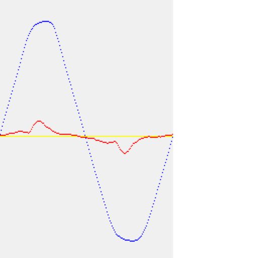
To start with I made maximum use of having the ESP32 accessible on the LAN. OTA firmware updates mean the electronics can be referenced directly to the AC meaning no distortion from a voltage sense transformer and the ability to capacitively couple the 120kHz signal without a pulse transformer. As this makes probing around with a scope a little tricky, I put in lots of debug over MQTT and included a webserver for graphical interfacing such as a snapshot display of voltage and current:
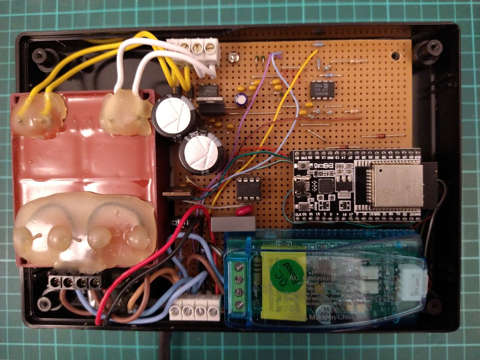
Everything has been made of stuff I had laying around so the Triac box & heatsink is way OTT but it doesn’t matter as there’s plenty of space for it next to the HWC
I would add an animation of the MQTT dash display showing the Joule buffer emptying but can’t seem to upload an mp4. Here’s a link to the animation and other images I posted on the buildhub forums where I spend most of my time,
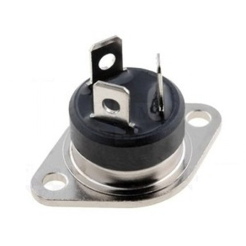
as critique - i would use surface mount triac. easier fixing when it fail at some point and better heat dissipation. just use push on connectors instead of soldering them on
Will bear FASTPAK in mind. Was actually quite restricted in choice for Alternistor types (AKA snubberless). Settled on Littelfuse Q6040J7TP this time although I could easily of picked a lower spec.
So I’m wondering what other people have come up with in the way of power routing? Most roads seem to lead to @calypso_rae and I’ve had an enjoyable time watching the Youtubes especially the one demoing the demo kit!
Obviously there’s a big attraction to a well designed and documented bit of kit like the Mk2 PV Router but I’m sure there’s still scope to take homebrewed router design a bit further. One thing I keep reading is that burst control is playing with ‘dirty power’ as is phase angle control. Some commercial offerings seem to make a virtue out of their patented sine wave modulation techniques - ‘lid off’ photos often reveal large toroidal power inductors which make me suspicious of phase angle control being filtered to remove harmonics but equally it could be AC Buck regulation.
I’m currently using burst mode and it’s fairly slow but totally adjustable. Currently my excess PV is very modest so the Joule bucket typically creeps up slowly and empties fast. I’ve yet to test it with higher export amounts and faster modulation. If it turns out to warrant more refined power control I’m ready to contemplate AC Buck topologies - I have plenty of experience with DC but synchronous flyback with 240VAC sounds like a big challenge!
That is where the problem lies. Quite heavy-duty filtering is required on both input and output, and that introduces huge difficulties for the switching devices.
To explain, think about a relay operating at d.c. The energy stored in the inductor (the relay) means the current must continue to circulate in the load to dissipate that energy when the switching transistor is turned off. A flywheel (or flyback) diode across the transistor provides a path for the current.
If you now translate that to an a.c. supply, the polarity reverses every half-cycle, and you have a very hard problem to solve.
One way (in concept) is to have a pair of switching transistors in inverse parallel providing the main current path, and a pair of flyback diodes to circulate the stored energy. But of course this won’t work, because the diode for one polarity of mains shorts out the transistor for the other polarity. Therefore, for each polarity, you need two active devices that must switch with perfect timing to smoothly transfer the current between the main path and the flywheel path. If the timing is wrong, there are either damaging voltage spikes or a short across the mains supply. One well-known make uses this scheme, and I’ve seen the result of what must have been a timing error in the switching.
Yep. Mosfet gate driving is definitely a non-trivial exercise. However, there are plenty of good gate driver IC’s around so it’s not out of the question for a DIY project. But it does demand good board design with attention to stray inductance and capacitance. Certainly not a stripboard project
I was just wondering about Shokley breakover for this kind of application - an inverse pair of SCR’s or Triac? I guess it’s the recovery times for repetetive switching or dv/dt behaviour. Must be something like that otherwise it’d be a go-to solution.
This is what the output of the one I looked at was like:
The FETs are chopping up the mains with a variable mark-space ratio to vary that average power, whilst the filters preserve the sinusoidal waveform, albeit at variable amplitude. Depending on mains polarity, you turn on one of Q1 or Q2 to supply the output (and the internal diode in the other one passes the current), and when you turn it off, you must turn on one of Q3 and Q4 to circulate the current in the load.
If you have nothing on and there’s circulating current, it’s bad news in the voltage breakdown department due to the stored energy in the filter. If you have one transistor in both series pairs on, it’s bad news in the over-current department (a short across the mains). Your problem is getting the timing exactly right to transfer the current between the series leg and the shunt leg every time you switch the transistors. And that’s before you think of interference that might turn one of the transistors on when you don’t want it on.
I experimented with it on my washing machine, Typically I might have a 1kW spare solar on a sunny morning but the element is a fixed 2kW so I annoyingly end up importing 1kW I would be happy if the washing took longer.
I had to replace the drive belt so while machine was open I tried the M028 module on the heating element it works fine, but there’s a snag - the logic in the washing machine has a timer, if the water has not reached temperature after 20 minutes it goes into an error state.
I have also experimented with it on a kettle - no idea how it works but the plug in socket meter I have shows the power factor ot the load changing considerably from 0.98 at 100% down to 0.2 at 10%
The page at CPC says “This power control module can control resistive inductive loads such as motors, heaters (if they are phase controllable).”, so there you have it - phase angle control. And that’s why the power factor changes: when it’s firing at 100%, the block of current is synchronous with the voltage (if it’s a resistive load). As the firing angle changes, the width of the current pulse changes, and its centre drifts away from the centre of the voltage pulse, so (if you smoothed the current out into a sine wave again) it looks like the phase has shifted, hence the power factor change.
Yes, although ‘shoot-through’ is evidently a problem solved in high power motor drivers where 100kW is the name of the game!
Currently looking around for gate driver IC’s designed for AC bridges but nothing doing. The other approach is full wave rectification and standard mosfet topology for synchronous buck. This would simplify the gate driving but the bridge would dissipate around 30W unless it too was derived from synchronous mosfet switches - but then back to square one.
So I’ve been running my diverter for just over a month now and I’m ‘leaking’ a little bit of power to the grid.
I have further refined the calibration of my power measurements by adding an optical sensor to time the pulses from my Elster AS300P (4000 imp/kWh) so I’m quite confident that my power measurements are decent enough.
However, if export power is only just tipping the balance by a few 10’s of Watts, and I sit and watch the electricity meter while the Joule bucket is slowly cycling (as witnessed by watching my Joule bucket animation) the bucket fills and empties cyclically for several 10’s of minutes - until the flashing LED on the meter suddenly goes on hard and the little tamper symbol comes up on the display. This evidently signals that power is going into the grid.
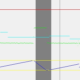
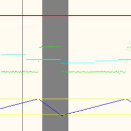
I have added another debug bitmap to my ESP32 firmware to see what’s going on in more detail on these occasions:
Each of the 256 horizontal pixels is a 20ms mains cycle (5.12s for the full image)
The Red line marks the (assumed) 3600J limit to the Joule bucket.
The Green trace is real power with zero half way up the image (as is cyan, but filtered)
The yellow lines are the upper and lower Joule limits of my dump algorithm (temporarily set low for investigation into the leakage)
The dark blue trace is the Joule bucket content as tracked by my software algorithm.
The grey verticals represent cycles when the Elster meter LED is on.
So in this example, my algorithm thought we were comfortably operating in the ‘unchallenging’ 500J to 1000J range yet after a while of this cycling (maybe half an hour) the anti-tamper symbol and LED come on. Clearly dead-reckoning the state of the Joule Bucket is bound to lead to inaccuracies over extended periods of cycling. I have not seen any prior discussion of this, but it seems inevitable to me.
As a resolution, the only absolute measure of the Joule bucket state is when the anti-tamper/LED shows up so I will max up the bucket content when this is detected. Likewise at the other limit, a deliberate periodic drain-down of >3600J (1Wh) every so often would improve accuracy at the expense of a little unnecessary electricity consumption. Can anyone tell me if I’m on the right track here?
In the long term, maybe. In the short term, like over one cycle of import/export, I’d question that.
I suspect the root cause of your problem is a non-linearity in your real power measurement, and experience suggests a likely cause is the phase error of your c.t. changing with the amplitude of the current. Because the import and export currents are unequal (which is to be expected) the changing c.t. phase error will mean there will be an error in the real power measurement in both cases (import and export) but the error will be different for export than it is for import.
You are relying on your real power measurement tracking exactly the meter’s, in both directions at different magnitudes and over an extended period of time. Short of a very, very expensive c.t., or applying a phase error correction based on the amplitude of the current (or maybe as well as), what you’ve suggested won’t totally remove the problem, because by the time the meter LED lights continuously, it’s too late - export has happened.
And I don’t see that there can ever be a total solution to the problem. For you to have a complete solution, you need to know the state of the meter’s “bucket” all the time, and that’ll never happen.
I have no feel for the magnitude of the phase error so out of interest I will try to characterise it over a range of power levels and see if it follows a reasonable polynomial. I already have an adjustable delay line to correct the obvious phase shift of the CT but I only set it up with a fixed resistive load in opposition to a reference load (two 100W lamp lives in opposition in the CT) so I will try switching in a 4-element halogen heater I’ve got handy. A job I’d rather be doing in the winter.
I suspect even three or four straight-line segments will make a big difference. The shape tends to be close-ish to a straight line with current plotted on a log scale, obviously the error increases with reducing current, as you’d expect from the way the magnetics work.
Yes that tallies with my observations of the error being more acute at low levels of export. Dead-reckoning your way along a path with lots of small changes in direction intuitively feels like you might get more lost than if you make fewer but larger steps.
The new 0.333 V 100 A one that will soon be in the shop measured a little under 1.88° at 160 mA, and 0.55° at 100 A.
Comparing that to the YHDC SCT-013-000, the last one I measured was 4.3° at 250 mA and 2.6° at 80 A (then it rose at 100 A as it started to saturate).
Both were reasonably close to a straight line against log of current.
On the subject of how the Elster AS300P meter behaves, I wasn’t expecting the 4000imp/kWh LED to be blinking while energy was cycling within the Joule bucket but evidently it is:
…shortly before the Joule bucket overflowed into export, an LED blink occured. This isn’t a one-off, impulses continue to track power flow in both directions until export is happening. I’m wondering if I could use this to keep track of the bucket contents… I know the direction of power flow from my own V*I measurements but I don’t know exactly where the turn-around point from import to export occurs in-between 4000/kWh impulses. At least it should remain in sync overall (not drift as it does now)
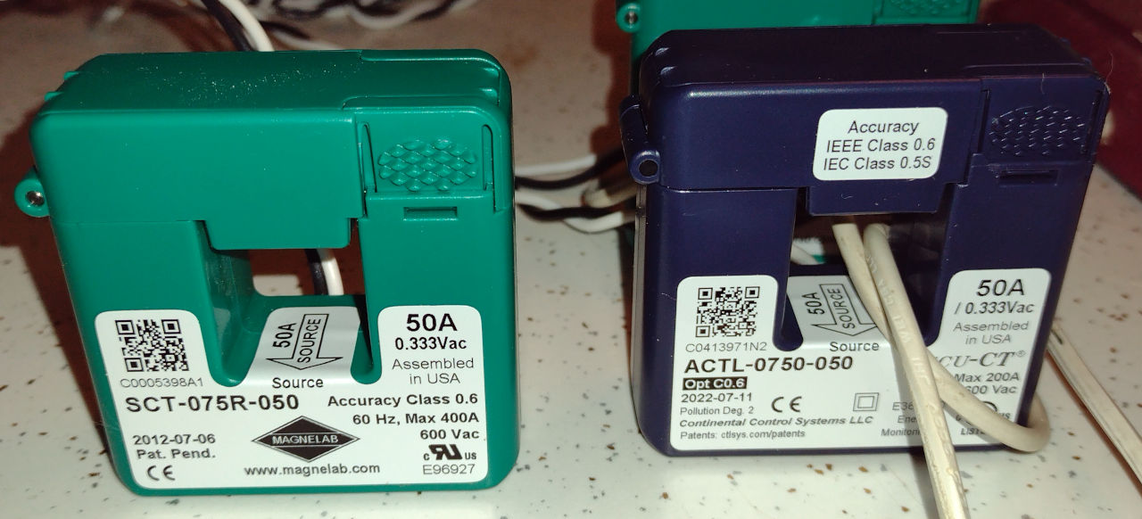
Spec’d as accurate from 10 to 120% of rated current, they appear to be on par with
Continental Control Systems ACTL-0750-050 Option C0.6 CT which is spec’d as accurate from
1 to 120% of rated current. I have four of the CCS devices and two of the Magnelab units.
They produce identical results when tested with the same load and same Wh meter.
(a Measurlogic DTS-307 which is a Class 0.5s revenue grade device)
Although it means very little, if anything, even the “packaging” looks the same.
Whether it’s collected on an imported item is, I think, somewhat discretionary - i.e. it appears to be waived if it’s not worth the effort to collect it.