It might be informative to accumulate the import and export energies separately and display those values. They should be identical, the rate at which they diverge and the point at which your meter shows an export will give you a guide to the error you have between import and export powers.
I thought I understood your problem, but now I’m not sure.
Are you saying you get LED flashes from your meter both for import and export? Or are “impulses” not the same as LED flashes? How do those LED flashes / impulses relate to the import register advancing?
When your diverter is supposedly balanced (but in reality not quite balanced), there comes a point when your meter shows an export. What happens after that - does it continue to show an export on each cycle of diversion, or does it recover for “tens of minutes” before repeating?
The other possible mechanism affecting the accuracy of your measurement could be the c.t. behaving as a high pass filter (which it does). The effect of this is to reduce the energy in the first half-cycle after a step increase in power flow (and vice versa), while it decides where the d.c. value of the output should be. I investigated this for Robin some time ago and he’s introduced a couple of lines in the software to equalise the filter, in effect extending the low frequency response downwards to mitigate the problem. All the details are on his website ( Faster Control Algorithm ).
I’m not quite sure what you mean by accumulating import and export separately? The accumulated energy in the Joule bucket is the accumulation of the instantaneous power (V.I) product for each sample taken over each 20ms cycle - but only while the power has (apparently) gone negative.
I suppose I could accumulate and display the imported Joules but they would merely continue the slope out of the bottom of the bucket which is currently at the bottom of the bitmap (out of bottom of bucket being import from grid; within the bucket being neither import or export and out of the top of bucket being export to the grid). I could center-up the bitmap traces for the Joule bucket (power traces are already centered) and mark the bottom of the bucket to mirror the red line at the top.
Impulses and LED flash are the same. In the export condition where energy is leaving the meter and entering the grid the impulse LED is on solid (as I expected from the videos I’ve seen). But when energy is slopping back and forth in the bucket the impulse LED is flashing irrespective of the sign change of the power.
As imported power is being cancelled by generation and slowly dwindling towards zero Watts, the impulses do as I expected and slow to a halt (no more flashes) when generation perfectly balances house load. What suprised me is that the impulses picked up again as generation increased and pushed the balance into negative territory (Joules now filling the bucket). Impulses continue to reflect the energy going up and down within the bucket.
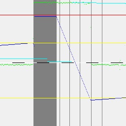
Here’s another example of an overflow:
Same trace desciptions but now there’s a black/white marker for the zero power level (0.5s per segment)
In this run the generation was only just overcoming consumption by 20 Watts or so (green trace starting just below zero line). A little after 1s in, the dark blue energy accumulated in the bucket was just hitting the upper limit (yellow) and tirggered the dump. Coincidentally, the meter flagged an export at this point despite the bucket starting to empty (you can just see the dark blue trace starting its descent). But I have amended the software to spot the export being flagged up and respond by instantly setting the bucket level to max to re-sync it. The dump load was 2kW so the rapid descent is marked by a series of impulses (about 0.5s apart). This is an example of impulses during energy cycling within the bucket limits.
Forget that. I’d forgotten - or maybe I’d been thrown by your statement that the absolute measurement accuracy was good because it’s been quite a long time since I worked on the diverters. In fact, calibration accuracy is somewhat irrelevant and only determines the frequency at which the dump load operates and stays within the meter’s bucket - it has nothing to do with the balance, which depends only on the measurement being truly linear in terms of real power.
The new name made me think there was a second source of data that you hadn’t mentioned before. So what you’re saying is a LED flash/impulse represent a quantum of energy of which several are required in order to fill or empty the bucket. And the LED becomes continuous when the meter’s bucket overflows during export.
Exactly that. 4000 impulses per kWh. Hence, when the 2kW dump load is energised from the time the export warning is triggered to roughly 2s when the lower bucket limit turns it off, we expect 4000/3600x2x2 = 4.4 impulses (we actually see 5).
I’m seeing a pattern though. When generation is beginning to pick up as the sun rises, quite soon I get the export warning as the bucket overtops, despite appearing in the safe zone to my algorithm. I can repeat this by increasing house load to create a balance and running for a while just on the side of import. Then, say, releasing 10W of load and allowing the bucket to start to fill very slowly, and then the kind of picture above emerges: my algorithm thinks it’s only just about time to turn on the dump load - but the Joule bucket is actually already full and the export warning trips.
So as you pointed out, the CT is not good at measuring small amounts of current, so a few watts going astray, after many minutes, can lead to a poorly sync’d bucket.
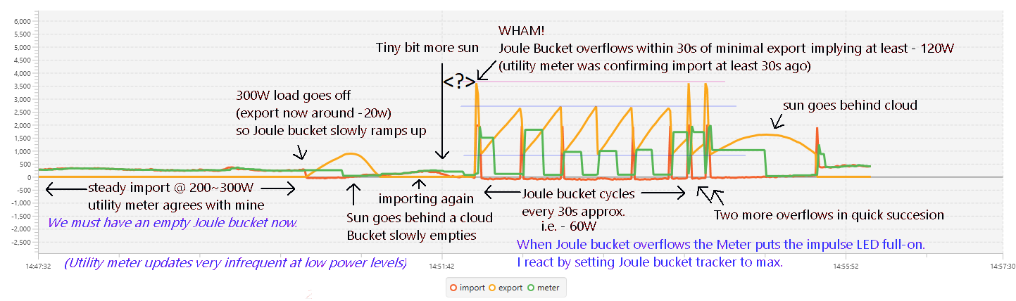
So far I’ve been looking at the small picture of events afforded by a 256x256 bitmap with each vertical written at the end of a cycle. i.e. 5.12s of history. There’s not enough in the way of resources on the ESP32 to do much better but to get the big picture I can chart the same parameters over MQTT at a resolution of one snapshot per second:
This “story board” of events illustrates my difficulty in working out what goes wrong. There are three traces:-
Red is signed real power as measured by the ESP32 and labelled import.
Orange is unsigned Energy in the Joule bucket as derived from the signed real power import over time and labelled export.
Green is unsigned power as measured from the impulse LED on the Elster utility meter.
Note that the latter measurements often lag the ESP32 samples as they update more slowly as power is reduced towards zero. At the zero balance point the meter impulses stop altogether. At higher power levels the update rate improves e.g. every 0.9s at 1kW. The trace really only serves as a confidence boost that the ESP32 sampling is sufficiently accurate.
The big question mark here is why the Joule bucket went from being demonstrably empty (a couple of minutes of approx. 300W import) to overflowing some 30s later. This implies that 3600J/30 = minus 120W of import was flowing into the Joule bucket despite the subsequent cycling showing what minus 60W looks like, over a similar period of time, and only half filling the bucket.
Because of this series of events I can’t see how my preferred explanation of poor CT current tracking linearity at low currents could explain what I’m seeing.
if you want track data faster on a larger scale i generally use upd push from an esp to a pi or general computer I do +100000 data points per second. which i can dump into influxdb from there example of that would be from wifi osciliscope in that case I am handling 8 osciliscope probes at once from a single esp and a mcp3008 IC you just need to write a shell script to push the incoming udp data to influxdb then just visulize it with grafana or chronograf or simply with gnuplot
That’s very interesting. I had discounted UDP for low-latency operation of the dump load when tests showed anything from 4ms up to 800ms from ESP to ESP. When I researched this I found many similar reports so concluded it was a fact of life. I didn’t test it from ESP to a different listener so maybe all the latency is in the listener. Thanks for the suggestion.
I assume you are familiar with UDP push there is no timing, no requests, no verification, data is simply pushed out to who ever wants to listen . so data points can come out of order and lost but that the point of UDP pushing lots of data in a constant stream that will ignore network delays and the correction is done at the other end - tcp sucked for this as the most I could do with my oscilloscope was <3000 data points per second . but for live visulization UDP it is fine and works well. since you are pushing 1000’s of data points a second you just need to average over X us(microseconds) to compensate for data coming out of order or lost
Yes but this frustrated me when I wanted to signal to a remote dump load to “burn” the following mains cycle: I broadcast the “burn” signal via the ESP32 doing the power direction monitoring via UDP and listened for the signal with the ESP32 driving the Triac. It was immediately apparent that the signal was significantly delayed on occasions so I set a GPIO high on TX and on the other ESP set a GPIO high on RX. Triggering a scope on TX, the RX would appear from between 4ms to 800ms later. This was cyclic, drifting in a regular pattern - as though the receiver was polling at around 1s intervals. I tried the Aysnc UDP libraries expecting an improvement but it was just as useless.
However, so long as the TX end responds directly then your scheme should work for me.
I’m pretty sure I 've misunderstood my utility meter impulse LED’s behaviour.
When I originally watched Robin Emley’s Youtube Single phase demo box for Mk2 PV Router I noted that his impulse LED was on constantly at the start of the demo, before the diverter was on, and while his PV was generating a healthy surplus.
I interpreted the constantly lit impulse LED as the meter signaling export taking place but it seems from watching another of Robin’s videos: Meter’s LED can be either on or off while diverting surplus power it really means the meter has simply ceased logging chargeable imports and may remain either on or off in this state depending on where it was in its blink cycle when importing ceased (joule buffer emptied).
In the light of this, my other interpretations were false - such as impulses occurring during the emptying of the buffer as I showed earlier:
In fact, I think the meter finally decided power flow had ceased despite me thinking there was a trickle of around 10W of excess power filling up the Joule buffer. This caused the impulse LED to give its final verdict that power was zero (the cyan line representing power at 4000imp/kWh drops to zero around this time) although I’m still slowly building up my model of the buffer (gently climbing blue trace to yellow max. buffer limit).
But on seeing the impulse LED coming on constantly, my ‘safety net’ firmware tweak mistakenly interpets it as buffer overflow and reponds by switching on the dump load and ‘emptying’ an imaginary ‘full’ Joule buffer - which the meter then clocks as chargeable consumption.
So, in fact, if ever I see impulses while I think I’m working in the buffer ‘sweet zone’ I ought to zero the buffer - exactly the opposite of what I have been doing.
As far as I’m aware, there is no defined behaviour of the LED, other than it flashes once for each quantum of imported energy. Many meters use a “continuous ON” LED to signify export, it would not surprise me if there are exceptions and I think you need to look at the meter specification to see if the behaviour is defined. It would also not surprise me if meters of the same type behaved differently, because the behaviour might have been defined by the customer - the owner of the meter.
Can’t find anything other than a sales pamphlet with a cursory spec for the AS300P although I have located a manual for the AS302P but it may have significant differences. Still not sure how many Joules it buffers - been waiting several days for the sun to reappear to find out now!
When it does emerge, I guess I have to establish a significant export (I think I can confirm this by looking at the ratchet and pawl icon on the LCD) then shut off the inverter and monitor the time it takes for the natural house import to start the impulses again.
Any more details on that aspect of your design? Do you send data over that, or is it just signal-on Vs signal-off? How far does that signal travel? Reliable? How much power do you inject it with?
It’s not encoded in any way, as it would be way too slow for this purpose - which is very low latency remote Triac firing sync’d to the AC. It’s proven to be very reliable in practice and I’ve yet to see a problem with range. Currently the CT measurement unit that injects the 120kHz is on the end of a 10m extension cable plugged into an outdoor socket ~10m from the consumer unit (to get to the meter cupboard) and the Triac unit is on a garage sub main some 30m away from the consumer unit. The signal is generated by capacitively coupling the output of a TC4427 mosfet gate driver that buffers an ESP32 GPIO pin.
It was in fact possible to position the timing of the signal to provide a burst just before the ZC such that a simple single transistor receiver could drive a MOC3041->Triac directly. The only issue being that it would be a bit risky leaving it up to an un-encoded signal like this. So the Triac box also has an ESP32 receiving MQTT that serves as an ‘enable’, relaying the X10 when appropriate. It’s been logging this and has yet to see a false trigger.
Yes, I think as bill-paying customers we should be able to rely on that. But this fact still leaves me in some confusion as to what happens in the ‘sweet zone’ of the Joule bucket.
I have now added the ability to get a continuous real-time scope like stream using websockets rather than the short 256 cycle snapshots I had before. Using this, I set about determining the size of the Joule bucket for once and for all. My method is simply to let the generation continue un-checked (dump load disconnected) for several minutes to ensure the Joule bucket has overflowed and power is going to the grid. Then, with generation stopped, I note how long before the meter starts charging for import again.
For one thing, this has made it abundantly clear that the meter’s impulse LED continues to flash during export as well as import. With around 180W generation going to the grid for a few minutes, the meter impulses show up roughly every 5 seconds (900J per impulse)…
…Then the generation falls and slowly crosses over into consumption. The Joule buffer (blue trace swinging between 0 and 3600J red markers) begins to empty after the power (green trace) crosses zero.
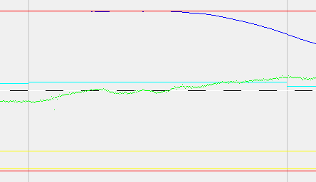
At this point, I would expect the Joule buffer to give up it’s maximum amount of leeway before the meter starts charging for import. But it doesn’t seem provide anything like 3600J. Zooming in on the transition from export to import…
…There only appear to be something like 450J to draw down from before the first import impulse appears (A reminder that the vertical grey bars show the occurrence of meter impulses and the cyan trace is the power inferred from their timing). The only time the meter isn’t charging either the supplier (leftmost impulse) or the customer (rightmost impulse) is in the narrow ~450J window in-between.
The upshot is that, unless impulses can happen when inside the sweet zone (in which case, who’s getting the bill?) then I have lucked-out with a teensy tiny Joule bucket.
The problem has always been that you can never know exactly the internal state of your supplier’s meter. And it’s my belief that meters from different manufacturers, different models from the same manufacturer, or even the same model of meter destined for different customers can behave in subtly different ways. Robin will tell you that the French “Linky” meter behaves differently to most British ones.
There might be an unwarranted assumption there - that an impulse is the same as a chargeable quantum of energy. It clearly isn’t when exporting, it might not be even when importing.
That is always a possibility. In theory, the meter should be able to charge you on a ‘per mains cycle’ basis, because that’s the smallest interval over which it can sensibly calculate the energy.
The most important point is, have you worked out exactly what is the proportion of energy that you’re being charged for when your diverter isn’t synchronised with the meter?
It certainly seems to be the case. However, when I first read about the principles of making use of the Joule bucket everything seemed to point to a standard 3600J. Unfortunately I wasn’t ‘into’ this when most of the discussions were ‘live’ so I might have got the wrong idea from mostly reading-up on Robin’s website.
However, this leaves me with more questions! How do commercial products get around this if there are no safe assumptions about bucket capacity? And if what you say about not being able to rely on impulses being indicative of charge then how does anyone know the parameters of their own meters when building Robin’s design?
I would take it that when exporting the impulses were indicative of the SEG payments if that had been prior arranged.
Do you mean ‘unnecessary consumption’ due to applying more power than is needed to the dump load? If so, and your other points about the interpretation of meter pulses means they can’t be relied on, then I don’t know how anyone could work out the proportion being charged for. Other than possibly switching everything in the house off - except for the diverter and load and checking the meter reading over a given period. But this reading is only to the nearest 0.1kWh so would need to be left for a long time to get a meaningful measure. Too long to leave the freezers off!
Most, from what I can see, don’t even try. There is often (possibly universally) a defined 'leakage" of export. With my cynical hat on, I presume it’s to ensure that the sales department doesn’t get complaints of “But it’s not working!” if there’s a momentary import and the LED flashes and the register increments. I think they are preying on human nature because the customer bought the PV so as to not buy a lot of energy, and then got the diverter to use up as much as possible of what they generate. Not using all but still getting paid for it won’t generate many complaints.
It appears that 3600 J is a common value, but it’s by no means universal. I think most people go about it in much the same way as you have - but often with rather less technology.
That’s one name for it. What I had in mind is, when you are consistently exporting, but there’s the occasional import, what does the Import meter read when compared to the generation meter. In other words, how much do you import as a fraction of your generation?
From memory, there’s a setting in Robin’s code to provide a small ‘leakage’ to export. You might want to add that.