Is it possible that the charge pump on the return (in photo) is not running , via software command from SMO20 when HP is open to buffer by the red diverting valve, so that route is “closed” and opens/runs when the diverter valve is doing DHW and the buffer heating circuit would not be on so not pushing water out? if so, would the purpose of the loop is some sort of safety feature?
That’s interesting. This winter I have been using about 25kWh/day to run my NIBE (F1155 12kW) Ground Source Heat Pump; hot water and heating for a 327sq/m house. I thought it was running high. I have 3x Tesla Powerwalls (40.5kWh) and on Octopus Intelligent, so paying 10p/kW between 11.30pm and 5.30am. Not bought a single peak unit since having batteries installed in September 2022. I have 9kWp of solar PV plus another 8kWp going in this month. So looking forward to sunnier days at 56° north!
Except it isn’t a coil - it can’t be.
I’d anticipate that the charge pump not running, would still leave the fluid free to flow round the loop as well as through the buffer. Depends on what the fluid feels is the path of least resistance, but relying on that seems a bit off.
However, and this is a key question, you said the thermistor tells the HP to turn on. What temperature is that reading - which part of the system?
If you switch the UFH on, does the HP and Charge pump turn on at the same time? If not, at what point does the HP/Charge Pump come on - what triggers it?
If it doesn’t come on immediately, then fitting a new manifold to the UFH may solve a large part of your issues as it will limit the temperature of the water in the slab, and slow down the rate at which the heat in the buffer is drained.
Agreed. Looks like the buffer tank is the one from this NuHeat webpage Buffer Tanks - How do they work with heat pumps? which talks about “To increase volume” and “Hydraulic separation” - so it’s just a tank, with four tappings. I have a Buffer Tank on my system and it’s just adding volume, to stop the heat pump short-cycling. (I reckon they would call it a Thermal Store otherwise.)
@prwv - it’s not entirely clear from the photos whether the bottom-right (blue) tapping on the Buffer Tank is connected or blocked-off. One of the photos and the PDF implies blocked-off - is that indeed the case?
@borpin - I always understood it was undesirable to have a blending value on UFH fed from a heat pump - the logic being that you don’t want to make the heat pump work hard to generate a higher temperature just to blend it down again before the UFH (which is Peter’s only emitter) sees it. My own UFH is fed from my heat pump without any blending.
I have the benefit of seeing the monitoring from Peter’s system which is showing a Delta T of 5 degrees across his UFH loops and a return temp of about 25 degrees which I don’t see the heat pump having any problem with,.
Good morning @dMb and @borpin
Thank you both for your advice and ideas yesterday. I had to work late into the evening so was unable to respond until now.
Before the work, I eventually got to a HP “expert” at Nu-Heat after two previous conversations with others from the technical department. He confirmed Brian’s analysis of the installation. He also told me that when the outdoor sensor reads 18d over a 24 hour period, the controller puts the HP into a form of Summer bypass to save it cycling.
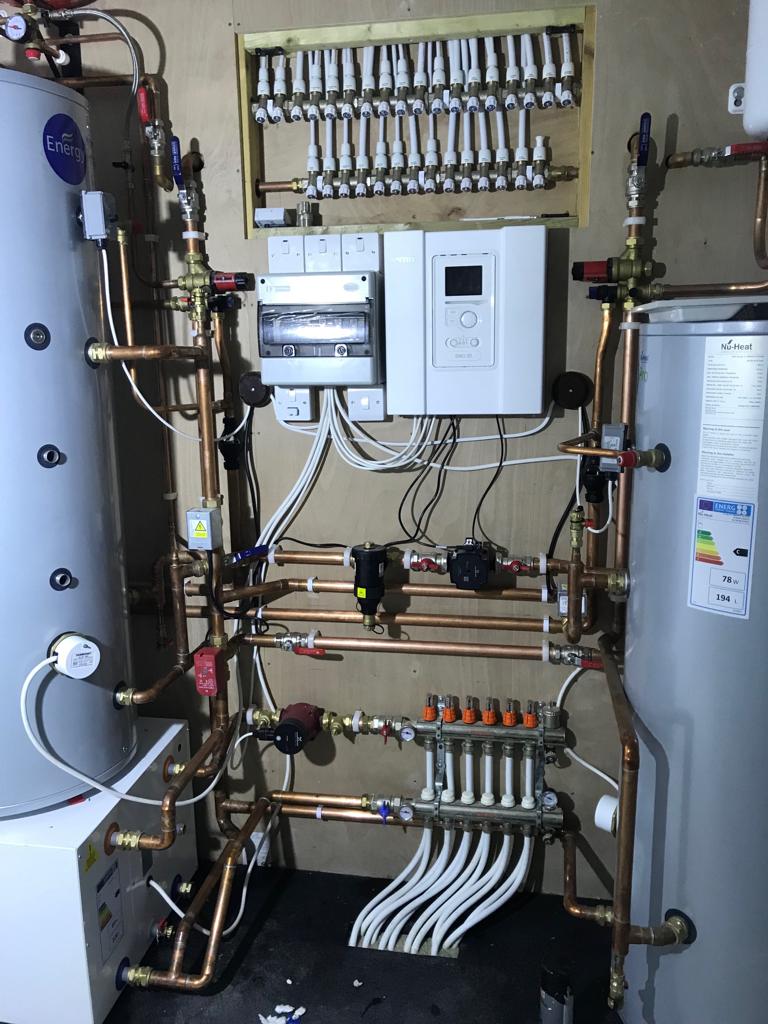
Until now, I have been under the impression that it was a closed coil feeding the UFH loop, much like a thermal store with the HP warming this fluid in the loop. One of three thermistors linked to the SMO20 control unit is attached to the buffer tank (you can see it in the photo, about midway vertically towards RHS of the tank). I presume this reports back buffer tank temp which is referenced to the WC curve to tell the HP when it needs to run to maintain the temp within the UFH loop. Brian, you are absolutely correct that the fluid within the UFH loop is combined with the fluid running through the HP/buffer tank. As we all previously discussed, there is no joined up writing between the systems and Nu-Heat have “designed” a system based on heat calcs they may have done for the size, layout etc of the house, although probably never quite appreciating the fabric and the PH element on sunny/cold days where the UFH loop is really not required. I thought that its overall use was minimal all the time, but with my partner on her own in the house for the 3-4 days we turned the heating off via the software earlier this week, the interior temp was clearly creeping downwards by perhaps as much as 0.4d per day, although had probably bottomed out by then.
I am now starting again in my head as the system is fundamentally different to how I thought it was. For those here who have gone through the process of a self build, you will appreciate there are an awful lot of things to take in and manage, whilst juggling work to pay for the build. I concentrated a lot on electrics and the automation as well as the internal plumbing of home runs from every destination, but missed or misunderstood this one completely. I apologise if I have wasted your valuable time and energy, but am still keen for any advice, as I still believe the running costs are excessive. My partner should have done another midnight HP meter reading to give past 24 hours, but she will not be awake yet to report back. Yesterday was 9KWh, up from3-4 when heating was off. The house is back up to normal temp I think, helped by mild weather outside.
1 Like
The Nu-Heat technician also told me that his commission sheet (a non electronic version will be at home) shows they left it on WC curve 9. This would have been a target temperature of 41 at 0d outside. This would have been far too much for my house I believe. I recall calling them back because, whilst I was outside a lot on site clearing duties etc, I was surprised how much the compressor was running. I imagine they dropped the curve back, because it was at 3, but I do not now for certain. A one year service by a NIBE approved agent moved the curve to 6 (34d) because it was his way of reducing the amount of start ups the software showed, which I guess equates to short cycles. That is where it has stayed but currently it is back to 3.
There’s no need to apologise for any misunderstandings Peter. You’re far from alone in having out-sourced an important sub-system of a new-build to people you had good reason to believe were experts in their field - and now it’s evident that’s maybe not the case.
From your PDF and your partner’s recent photos (and the knowledge I and others have of how NIBE systems work) we can all understand what’s been installed, how it was intended to work and how it’s actually behaving.
I’ve got a broadly-comparable system to yours:
- NIBE heat pump of a similar age with effectively the same controller
- Mine is an F1145 GSHP with the controller built-in
- DHW and Heating outputs
- My Heating circuit has a Buffer Tank to add volume and the UFH uses the same inhibitor-protected water as the rest of the system; I do also have a separate Low-Loss-Header for ‘hydraulic separation’ whereas your Buffer Tank performs that function - or at least attempts to
- I probably have similar heat loss - e.g. yesterday I used 8.2 kWh of electricity input across space heating and hot water, with 31 kWh of heat output for space heating
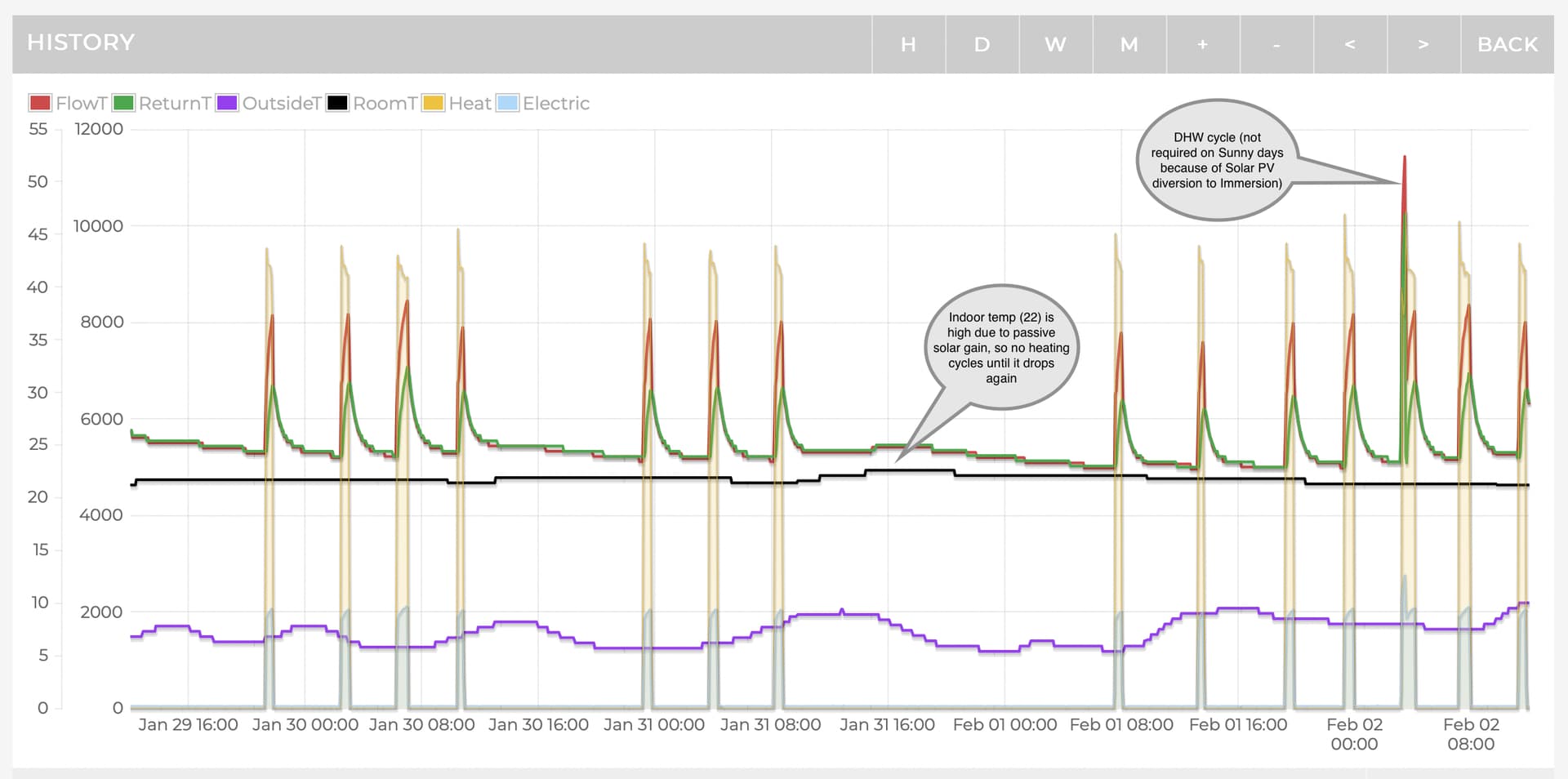
I’m on Curve 5 which is working well for me. As noted previously, I have the “problem” of passive solar gain on cold-but-sunny days so the Indoor temperature sensor effectively “lowers the curve” when the house goes over its target temperature, having the effect of pausing the heat pump cycles until the house cools back nearer to target. Sample graph from MyHeatpump app shown below:
1 Like
This sensor must be what NIBE Uplink calls “external flow temp.” with parameter ID BT25. NIBE’s manual for the SMO20 confirms that BT25 is connected between terminals 8 and 10 on the X2 terminal block and the Nu-Heat PDF shows what they call “Temperature sensor external supply line” at X2: 8, 10 so that all matches up. (Their PDF shows it on the pipe beyond the Buffer Tank rather than on the tank itself, but hey.)
These NIBE controllers effectively work like this:
- They read the Outdoor Temperature Sensor
- They use the configured Weather Compensation ‘Curve’ to look up the Target Flow Temperature which is predicted to offset the heat loss at that Outdoor Temperature (and they report this via NIBE Uplink as parameter ID S1, the “calculated flow temp.”)
- They then cycle the compressor On and Off so the actual flow temp (measured as BT25) averages out the same as the target flow temp (S1)
The actual flow temp will be lower than the target when the compressor is off, so the controller counts how much lower the temp is (how many degrees) and for how long (how many minutes) and keeps a running total of these “Degree Minutes” (reported as NIBE Uplink parameter DM). When this number goes too far negative (a configurable setting at location 4.9.3 in the controller) it starts the compressor.
Then, with the compressor running, the actual flow temp will be higher than the target, so the DM value gets less negative - and when it reaches zero the compressor shuts off. There’s still heat in the pipes from the heat pump so the DM value goes positive for a bit and then starts dropping again. When it gets back to the configured value the compressor starts again.
Too many start-stop cycles shortens the life of the compressor, so from a compressor lifetime standpoint you want fewer, longer cycles. That means having the 4.9.3 value set to a big, negative number; my system is set to -500 which today (+8 outside) is giving me a 45 minute-long ‘run’ about every 4 hours. For me that’s fine, since my house is very well insulated and has a high thermal mass so the internal temperature has been rock-steady at 21.1 all day. With less insulation and less thermal mass the temperature might have started to drop so shorter but more-frequent ‘runs’ might be preferred.
Edit: I’ve just spotted Peter’s actual heat pump shows up as an F2040-8 in NIBE Uplink as a ‘slave’ of the SMO20, and it does have inverter control (unlike my older GSHP unit, which is only ever On or Off). Time to amend by NIBE Uplink script to grab all the extra parameters…
1 Like
That would be true if you were running it directly. As there is a buffer tank, that should act as,well, a buffer.
I also don’t see the logic at running the HP at such a low flow temp unless that is its most efficient state?
If this was fine, the HP would not cycle! For right now, but what about in the shoulder months? You could easily get a much reduced delta.
Personally, I suspect it simply cannot modulate down low enough.
I don’t monitor my UFH temps in all honesty. I am thinking of replacing the TRV with a web MQTT enabled TRV so I can control the flow temp - increase to heat quicker and decrease to prevent overshoot (which honestly I don’t get much of as I control to a 1/10th of a degree). I also have an automatic bivalent valve that effectively feeds the UFH from 2 different parts of the tank starting at the bottom of the tank and sets the flow temperature there as well.
If does demonstrates how difficult it is to design these systems and suppliers just roll out a standard setup, charges a fortune, then just walk away.
The more I read the more I think I was lucky with my system. However, I have recently worked out a major flaw in how it is installed that I need to correct. Currently the Boiler only heats the top 1/3. I’d be better heating the whole tank to a lower level. I’ll get it modified this year.
1 Like
I installed the sensors as I completed all the wiring. I installed it at the pdf, but the engineer who commissioned it on behalf said words to the effect of " oh I know the manual says there but we have found it is far better here" and moved it. Hence why it does not look as tidy as my original placement!
Regarding your edit @dMb, I was confused because I believed it had inverter control. I look forward to the new data.
Sorry, I cannot type. I meant above, " your edit" and “inverter”.
[Fixed - Moderator (RW)]
I was confused too, because the graphs of Flow and Return temps look roughly like mine, which is firmly an On-Off affair, but yours definitely has an inverter (although so far I’ve only spotted it at either 0% or 62% speed)
The extra data is being logged as of about 17:20 so only a couple of hours’ worth so far. I’ve already spotted something which looks fishy though: of 5173 total operating hours it’s spent 4018 hours doing (what it thinks is) Hot Water heating so only 1155 of Space Heating. By comparison, my system is showing 3825 and 217. This further reinforces my hypothesis that the UFH loop is actually pulling from the DHW cylinders, for reasons I don’t understand.
1 Like
Hi @prwv - could you provide some more info about how the DHW cylinders feed hot water to the house please. From the photos it looks like the hot water take-off pipes from the top of both cylinders go through the back wall of the cupboard. Do the pipes join together behind the wall - so there’s (expected to be) balanced draw-off from both cylinders - or does each cylinder feed distinct sets of hot water taps / showers?
Your dual cylinder installation is a little unusual so I wonder if (part of) the problem is related to you having the two cylinders and whether we could do some tests by shutting one of them down. That would only be practical if they do work in tandem.
Via these manifolds I installed. Cold water top row, hot water bottom row, all joint free home runs to their individual destinations, 10mm to basins and lavatories, 15mm to sinks, baths & showers. In each case the manifold is fed from both ends. They do indeed work in tandem, with equal draw down. The sensor is only on the left hand cylinder; I guess the theory that, with equal draw down, any reduction in the left cylinder is mirrored in the right hand one. I did consider shutting one off for periods when I am not there, but have never done it.
2 Likes
Thanks Peter. I completely agree that’s the best way to run hot water pipes in a new-build (small-bore pipes direct to each fitting from a manifold) to get hot water within a few seconds at any fitting without the complication and losses of a pumped DHW loop. I did something similar (just for the hot though) using 12mm MLCP pipes which seemed to be the sweet-spot for my use case, because of some quite long pipe runs. (On reflection it would have been better if the DHW tank had been more centrally-located in my house, not at one end of the second floor.) I wrote up my research at Domestic Hot Water Pipe Sizing | Marsh Flatts Farm Self Build Diary in case anyone else is considering a similar approach.
So we would have the option to isolate one of the cylinders and you’d still have hot water; good to know.
1 Like
On extra, brief note. You will notice the slightly jaunty angle of the UFH pipes, which were obviously put in at the slab phase. They were correctly sited but we were obliged to leave two specific empty lengths of pipe on the main F&R, notated on the pdf, incase a regulatory body chose us a guinea pig to install heat meters for statistical use. It ws Nu-Heat who informed us of this. I never found out who would pay for the plumbing element if we were chosen!
1 Like
That classic, if only ![]() . Yes I concur; should be a fundamental part of the design, not shoehorned in later! My next house will have the shortest runs possible (if I ever find some land).
. Yes I concur; should be a fundamental part of the design, not shoehorned in later! My next house will have the shortest runs possible (if I ever find some land).
1 Like
Peter and I have been exchanging messages offline so this update is less for him and more for Brian and others who have kindly contributed to this thread - and for those who come across this via a search in the future. Peter has given me permission to share screenshots of some graphs and dashboards.
What We Know
We know that when the heat pump is set to not attempt space heating but still manage the hot water it’s working broadly as we’d expect:
- It heats the DHW tanks when those fall below the configured temperature threshold
- In the absence of any DHW draw-off the tanks cool at a reasonable rate, losing about 5 degrees in about 18 hours (similar to mine)
- The daily electricity consumption is also reasonable, typically 3 - 4 kWh, which is perhaps a little high but not ridiculous
We also know that when the heat pump is set to attempt space heating the monitoring data looks very different. Note that the UFH circulation pump has been running constantly since 14:05 on 2nd Feb, to ensure that any heat available is distributed to the floor slab:
- The DHW tanks are losing temperature 12 times faster than normal, typically losing 5 degrees in 90 minutes
- Not surprisingly, this prompts the heat pump to run a hot water heating cycle about every 100 minutes
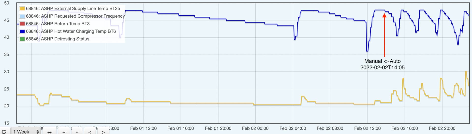
The graph below shows the transition from ‘Manual’ (no attempt at space heating) to ‘Auto’ (space heating) with the red arrow marking the pronounced acceleration in the rate of cooling of the DHW tank (blue line shows the DHW tank temperature).
The mustard yellow line is the temperature in the UFH buffer tank, which shows periodic peaks, typically at the end of a DHW heating cycle (which is to be expected).
Conclusion
The conclusion is that the UFH loop is somehow managing to take heat from the DHW tanks. The only mechanism by which that could be possible is effectively using those tanks as Thermal Stores by running UFH water through the DHW tank ‘heating’ coils.
Hypothesis
The current working hypothesis is that the NIBE VST11 Shuttle Valve which is intended to divert the heat pump flow to either the DHW tank coils or the buffer tank (but never both) is not working correctly and when set to ‘buffer tank’ (B) is actually allowing water to flow both to the buffer tank and the DHW tank coils. This in turn is allowing the UFH circulating pump (and / or the heat pump charge pump) to move water through the DHW tank coils too.
Peter is going to contact Nu-Heat for a recommendation on how best to proceed.
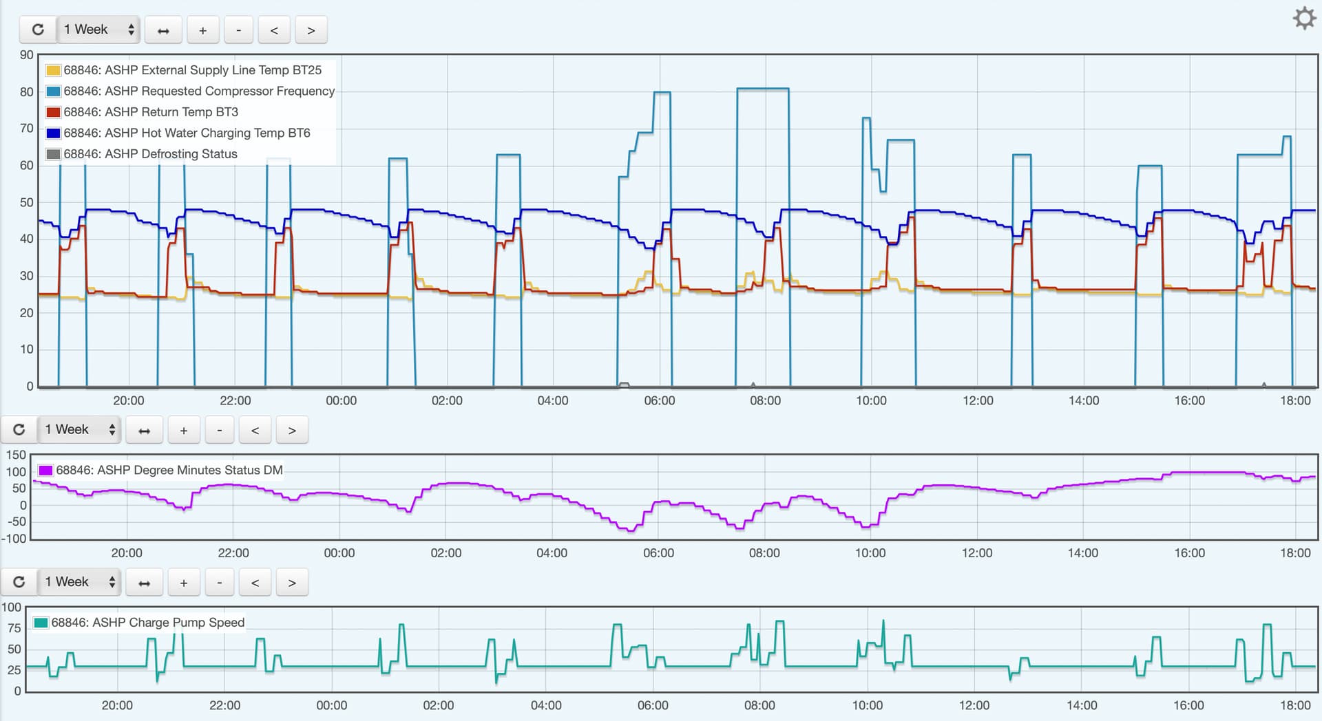
Here’s a rather more comprehensive view of the most recent monitoring data, reinforcing the fact that the heat pump is running frequent DHW heating cycles. No wonder it’s using more electricity than it should be.
3 Likes
@dMb @prwv Very interesting thread. Now I have got David’s NIBE Uplink API guide implemented, it’s going to be good to compare with other set ups. I have a fairly similar scenario. 327m2 house. Constructed in 2015, it’s not passivhaus, but we did have to put in extra ventilation for it to get a completion certificate as it was “too airtight”! We’ve got a 12kW NIBE F1155, 750 metre horizontal ground collector, a 400 litre hot water tank and wet underfloor heating throughout the ground floor. We opted to have radiators upstairs due to having a child with a bad heart problem (very sadly no longer with us…) but it was suggested we would not need them. We actually had to put in a few more radiators and upsize some to meet conditions for Renewable Heat Incentive payments. We are a family of four (kids 2 and 7) and I work from home; so fairly large house and fairly high demand. This winter the GSHP has consumed about 23kWh electricity per day. I thought that this was good, but it’s 2.5X David’s average on emoncms! If I am reading the figures correctly. Out of interest, how does emoncms calculate the heat output and COP?
1 Like
If the UFH pump is running continually, it is little wonder the tank temperature drops. What tells it to run? It should only run if the Room Stat tells it to. This is a fundamental flaw in weather compensation systems. They often attempt to call for heat because it might get cold, but are unaware of other factors such as Solar gain, number of people in house etc. I think the house probably gets overheated.
Are you sure the flow through the DHW tank from the HP is through a coil? I’d expect it to be heating the tank direct and then the DHW flowing through a coil to heat that.
I’ll still go back to the blended flow to the UFH. It lowers the temp of the water in the slab and then gradually draws down the buffer tank. You then kick the HP into action once the Buffer tank cannot supply a flow that is higher temperature than the UFH flow (if the UFH is running).
The UFH pump should only be running if the Room Stat demands it.