Just over two two weeks ago I bought a Raspberry Pi 3B, some Wemos D1 minis and 5 DS18B20s. The aim was general home monitoring including the Midea 12kW ASHP, the flow and return temperatures across the plate heat exchanger isolating the the heat pump from the radiator circuits, the SolarEdge 6300kWp with 2x10kWhs of battery, my weather station and Solar forecasts, and electric consumption by the ASHP.
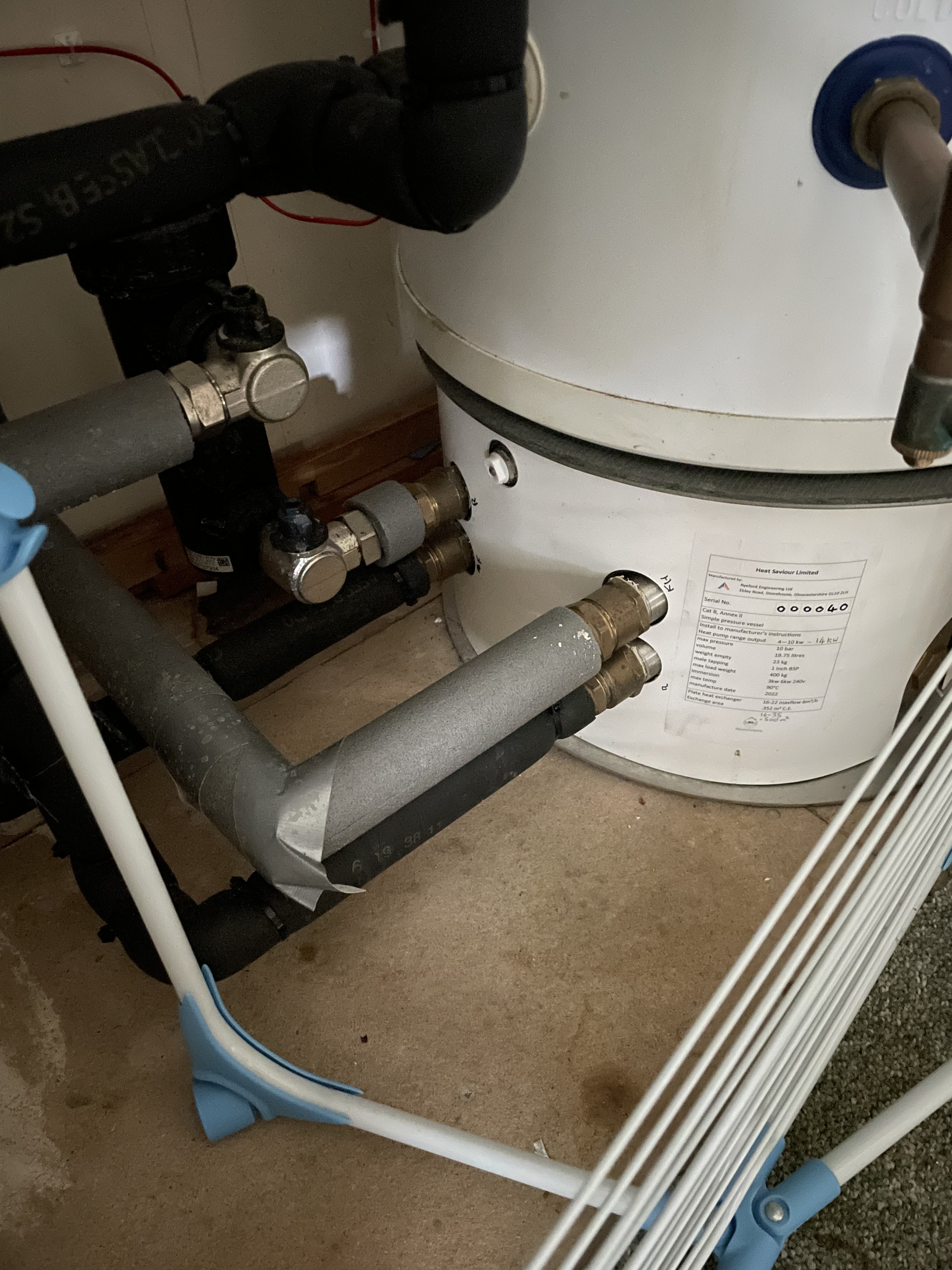
The heat pump and DHW was installed mid May last year. I had all the 21 radiators replaced with low temperature ones, but left the pipework alone as it worked at 40C with the 9 year old Vaillant combi. We had a hot water tank reinstated sitting on top of a Heat Saviour plate heat exchanger with a 0.5 m2 area (estimated at 12-16 kW capacity depending on temperature). The whole house is about 300m2 achieving an EPC of 78 prior to the changes. It has triple glazing, cavity wall insulation and 300mm fibreglass in the loft with 3m eves as it’s a chalet that have about 100mm.
It wasn’t until November that any serious amount of heating was needed. For fear of a big electric bill we only ran the upstairs heating initially set at 38c flow without weather compensation. The towel rail temperature was 30c peaking briefly at 32c. In December at below zero temperatures with almost 24 hour operation we barely achieve 17-18c room temperature upstairs (the downstairs lounge was heated by a wood burner. At the end of January the Solar and batteries was installed and I started heating the whole house on the GO tariff!
I then started looking at the renewable heating hub site to see if the heating system was running efficiently. I had daily estimates of heat consumption based on what the appliances were using and the grid + solar as the installer refused to add the electric energy meter and the Midea reporting was dubious (reporting a tank buffer heater that was not installed). To date the pump has used 2800kWh which is better than 12,000kWh hours in previous mild winters.
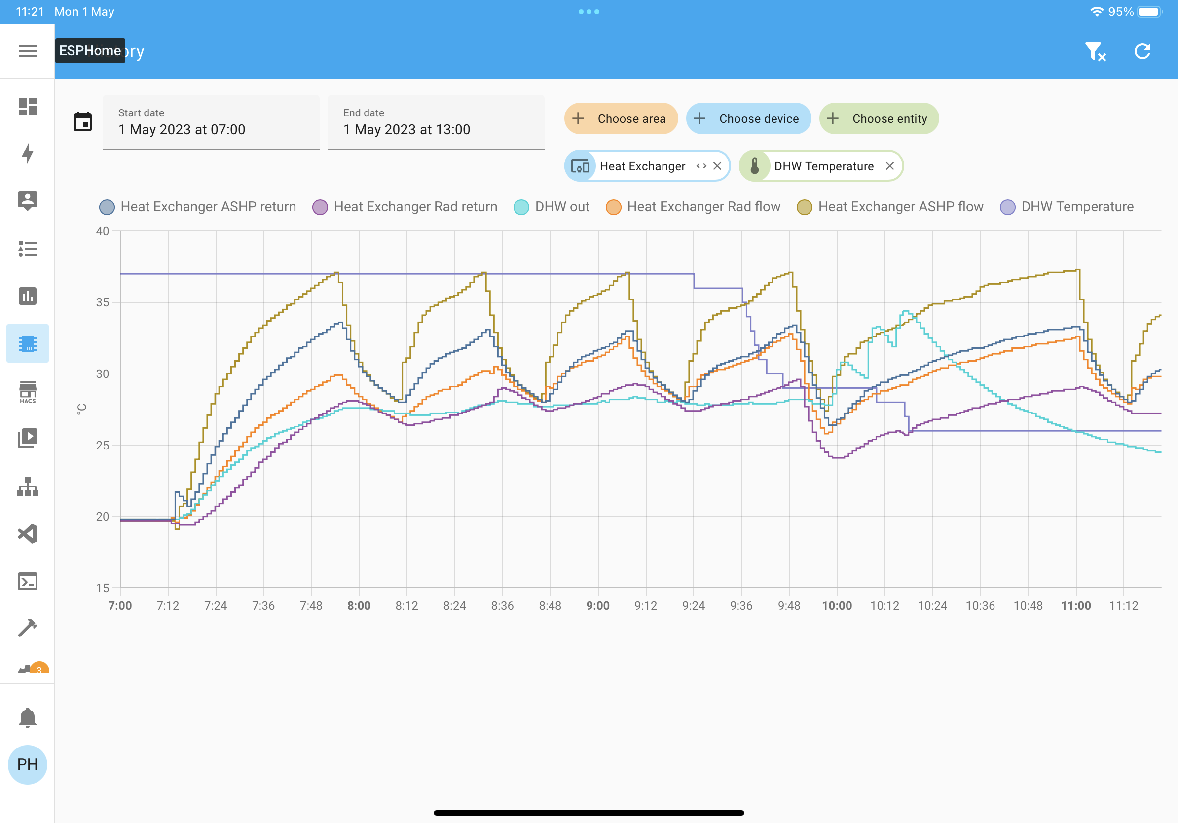
It has been a steep learning curve. Last Thursday I started getting the Wemos D1 mini talking to ESPHome and then the temperature sensors. Last night I added the temperature sensors to the pipework and this morning I got the monitoring data! I’ll post photos below. Just to explain I ran the upstairs bedrooms and downstairs living areas till 10pm and then turned on the downstairs bedroom zone to see how much longer the heat pump would run. The temperature sensors show that the ASHP is delivering to the 35c the WC requires and that the heat exchanger radiator flow temperature is consistently about 5C below the input temperatures. There is a massive secondary circulation pump (Wilo Top - Z25/6) which consumes at least 110W on the slowest speed!
Perhaps @johncantor could give advice as this morning I watched his opencms video on types of cycling.
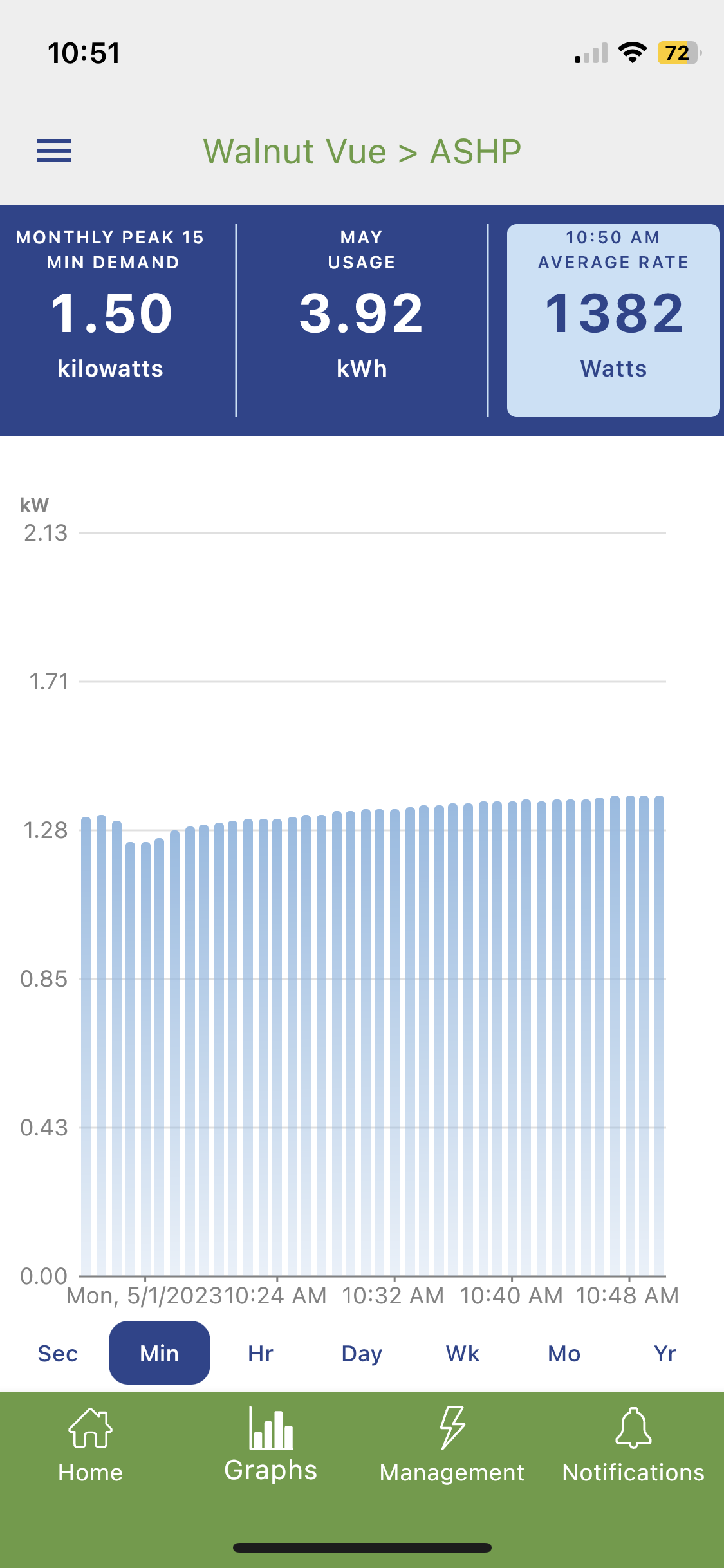
P.S. The Midea wired controller reported 6.4kW heat output at the time I captured the Emporia power graph. So COP with some reduction for the secondary circulation pump was over 6.
I put together a calculator here Heat pump & heat exchanger calculator to calculate expected performance impact from a heat exchanger. Might be useful for your investigation process there.
It’s suggesting a drop around 3K for the default conditions in the calculation and a COP impact of -0.15, that’s probably underestimating the impact, it doesn’t take into account the secondary pump.
One thought is to check that the heat exchanger has been plumbed in in a counterflow orientation? Ben @thedawnbefore had an issue with his heat exchanger which was plumbed in incorrectly.
If you think of the direction of flow in the primary circuit, say going in at one side of the heat exchanger coming out the other. The direction of the water flow in the secondary circuit should be moving in the opposite direction, water coming back from the radiator should be going in at the same end as the port for the primary return, the water going to the radiators should come out of the same end as where the primary flow water enters the heat exchanger… a little hard to describe, hope that makes sense
I note that the heat exchanger rad flow never reaches a temperature that is higher than your heat exchanger ASHP return which would be the case if the heat exchanger had been plumbed in incorrectly for parallel flow.
What you’re trying to say is, the temperature difference between the water giving up heat and the water acquiring heat is the same all the way along the heat exchanger. So hot flow in the primary circuit enters at the same side as warmed water in the secondary circuit exits the heat exchanger, and cooled water in the primary exits from the same side as cold water in the secondary enters.
My understanding is that it is counter flow. The flows are diagonal opposite.
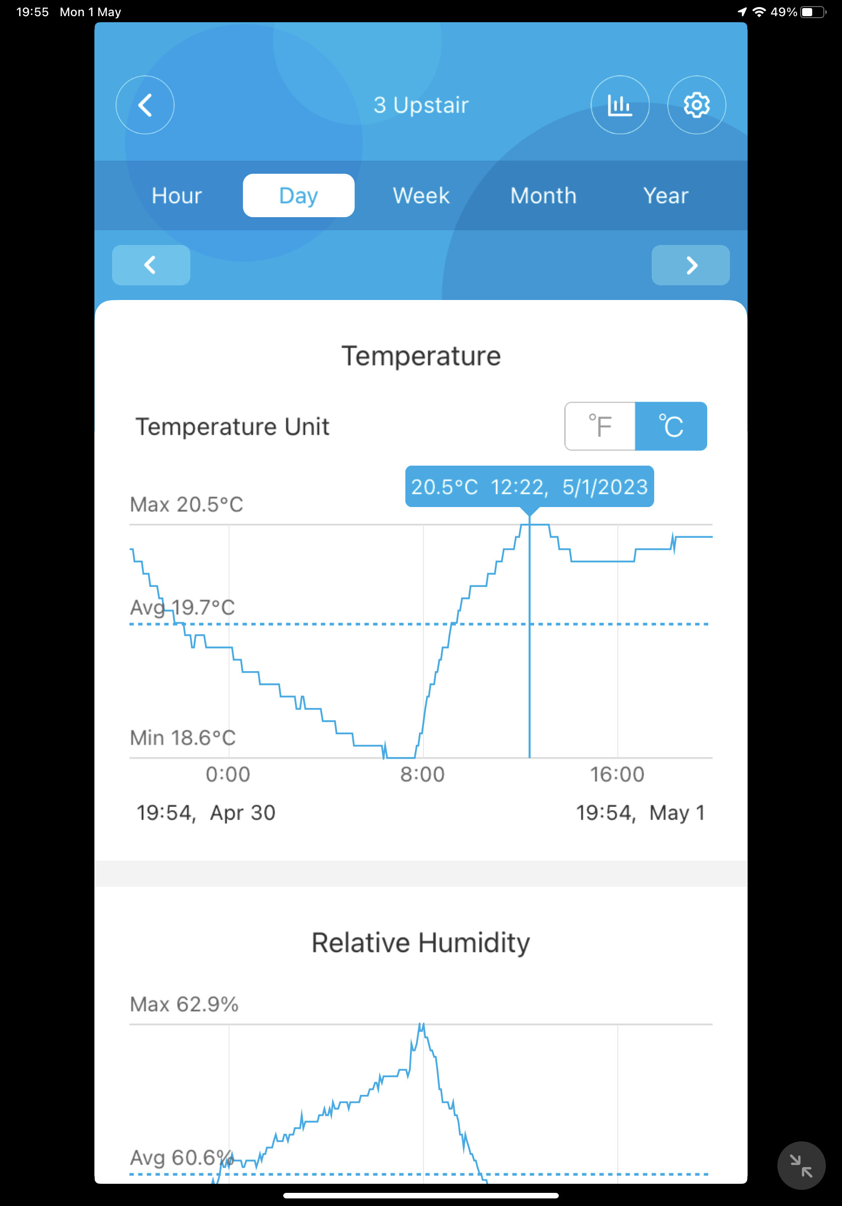
I played a bit with the heat exchanger calculator. It predicted much higher temperatures, but clearly the Midea is cutting out when the temperature is about 3c above the target temperature for a sufficient period of time. I cannot manually set the target flow temperature below 35C - this is a silly restriction. The Govee in the upstairs bedroom showed a 2C rise over nearly 5 hours (see below). This morning’s run from 7:15 to 12:00 used about 5.5kWh of electric even with all zones on. There was no interruption from the zone thermostats and the TVRs are fully open.
The secondary circulation pump is capable of up to 5.5m3/hour! It’s on it’s slowest setting. The motor is pretty hot. Personally I’d prefer a Grundfoss Alpha 2 adaptive pump, which would have been a bit cheaper. I’m no expert. The installer wanted to be sure as we have 22mm pipework distributing over a 10.5 m x 14.5 m box on two floors. The rads are fed by 8mm and 10mm micro-bore mostly relatively short (mostly 0.5m to 3m with one leg longer by the length of the radiator). One new radiator was added with 15mm pipe - it doesn’t get any hotter.
I don’t think the pipework would explain the 5C drop on the flow temperatures either side of the heat exchanger rather than the predicted 3C. Nothing I could do with the calculator could bring that about. It is immersed in a 20l buffer vessel. I don’t know whether the primary flow goes through the buffer as well or whether it is a jacket which indirectly heats up. I do have to top up the secondary circulation loop up when it drops below 1.5 bar to 1.2 bar. The new radiator frequently (every few weeks) needs bleeding, but not the others.
I guess I should pass it over to the installer. It’s their own heat exchanger! Any thoughts @johncantor.
You mean it’s actually plumbed for counter-flow, or that’s how it’s intended to operate?
As Trystan noted, the fact the “Heat Exchanger Rad flow” is often closely following but is lower than “Heat Exchanger ASHP return” does suggest the heat exchanger is (incorrectly) plumbed for parallel-flow.
Definitely one to refer to your installer. Show them your graphs and ask them to explain why the rads are only seeing 30C when the heat pump is sending 38C.
I suppose I assumed the connection instructions for the heat exchanger would be to achieve counter flow! The plumbing is as per the instructions but the evidence points to parallel flow. A good plate heat exchanger should achieve 1C temperature difference between the two sides (side A flow in and side B flow out).
Without knowing the manifold arrangement for the plates it is not possible to draw conclusions from the pipework, but common sense suggests that for counterflow the the hot sides are on the same side if the plates are stacked vertically.
I have booked a service in two weeks time. I will hand over my findings after the service and before the 1st anniversary of commissioning.
As someone who installs plate to plates, this will not be plumbed wrong it’s mass produced. So potentially there is either a blockage in it restricting the transfer of heat or the heating circuit pump is too fast and the return flow is going through the plate to plate too fast to heat up so is only giving you 30 degree flow.
This was one of the possibilities as the secondary pump is a Wilo TOP Z25/6. It can pump up to 5.5m3/h! I have set it on the slowest setting rather than the highest as left by the installer.
The plate is made in Eastern Europe if I remember. It’s a Heat Saviour.
I guess that unless the installer fits a smaller pump there is no way of knowing.
The hex itself will be manufactured correctly but you still need to connect primary and secondary pipe work correctly? That’s something the installer would do - unless it’s part of a pre-plumbed setup?
The way I look at the heat exchanger is that at every point heat will flow from the cooler side to the hotter side (a consequence of the second law of thermodynamics ). The optimal situation is that the radiator (secondary circuit) will be cooler than the heat pump (primary side) at every point, otherwise the net transfer across the entire surface consisting of many parallel plates will be reduced. The purpose of counter flow is to maintain a uniform temperature gradient along the primary direction of flow without inversion which would result in heat being transferred back to the primary.
The rate of heat transfer will be proportional to the temperature difference either side of the plate. The effect of an excessive secondary flow rate will be to reduce the temperature rise on the secondary side (effectively greater volume to heat with the ‘fixed’ heat transfer across the plates). Now this is ok provided the goals to maximise the transfer of heat from the primary to the secondary and the total heat produced by the heat pump are achieved. In other words the secondary side should be driving the primary up to the maximum output it can produce and then maybe down to equilibrium. In time an equilibrium will be achieved in which the secondary flow temperature gradually rises, and as a result the secondary flow temperatures leaving the heat exchanger should come close the primary coming in to it.
In my case in this milder weather (I’ve been monitoring for a week) the heat pump is unable to modulate its output lower and the flow temperature rises above its limit so it cuts out. 35c is the lowest I can set it.
I would agree with that but if the secondary circuit is sapping the heat transfer by either the flow rate being too high or the convected heat into the room is so great that the water temperature in the system falls greater than the 5c delta, then the plate to plate will never achieve the 1c differential between heatpump flow and secondary flow.
Simple trial would be to turn off all rads except the furthest one away from the plate to plate and see if the temperatures come closer?
The various cycles in the first post show the rad flow temperature converging on the primary return temperature over several cycles but never going above. I’ll try after the heating finishes while the secondary water is still slightly warm. I suspect it will not exceed the primary return though.
My own view is the plate heat exchanger is not plumbed for counter flow and the secondary pump does not need to be as large. I think a Grundfoss Alpha 2 adaptive pump would be better, but I’m no expert.
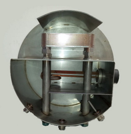
I’m no expert either and far from it but plate to plate piping can’t really be done wrong because it’s either diagonal flow and return or parallel flow and return through the plates, do you have pictures of your setup or the name of your heat exchanger. I am baffled because I run a buffer and here’s my flow and return temps and they are only a couple of degrees apart.
It’s called heat saviour and a google should find it. Mine has extra plates to increase the maximum transfer rate. My interpretation of the photos is that the flow directions are parallel (left to right) rather than anti parallel (counter flow).
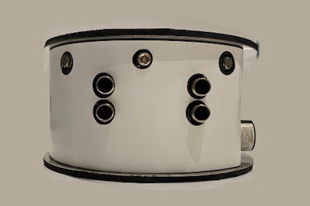
I have never used one of these so the next question might seem daft but how do you fill the buffer tank and circulate the water from it, from the looks it appears to be 4 pipes going through the buffer into the plate to plate with only the pipe work heating the buffer water. According to heat saviours manual the plate to plate is totally reversible depending on your situation. If you know how your buffer is filled and works let me know because I can advise what to try to correct it. Is your circuit plumbed into the top ports or the lower ports.
I must admit I thought the heat transfer to the secondary flow return pipes would be somewhat limited. I don’t have an immersion fitted in the buffer for emergency backup heating. I suppose the buffer is filled before the DHW tank is placed on top, However, there is a bleed valve and blank that could I suppose be used.
The primary flow is bottom left and secondary flow to circuit top right. The Mag clean is on the secondary return top left. Hence the parallel flow. I guess the pipes can be swapped by only isolating the flow and return at the pump and mag clean.
The photo below from the article on parallel versus counter flow illustrates situation well. I think I was wrong to suggest parallel flow can cause crossing of the curves, but at some distance under some circumstances the primary and secondary temperatures equalise. If only half way along the travel distance (area) there will be a drop in heat transfer capacity. The other limiting factor is the maximum temperature being at least delta T below the flow temperature. rather than 1c approximately. My radiators were barely achieving 32c with 42c flow in the really cold weather.
Thanks again for your advice, which is most welcome.
As you know the idea of the buffer/volumiser is to add volume to your system but I fail to see any advantage of just having a 20 litre tank with water sat in it and not circulating. If you are using the plate to plate to create separation so you can use glycol on the ashp side and water on the circuit side then I get that, but if you are not using glycol then I can’t see the point in using it at all. You will loose efficiency from using glycol and loose efficiency across the plate to plate so potentially 3c degree loss before it gets to your heating circuit.
So as your primary flow goes through the buffer you will be losing heat because that stored water will be sapping the heat out before it gets to the plate to plate likewise your circuit flow from the plate to plate will do exactly the same and that’s where your losing all your heat. If your system is hot water priority then when the water is on then that buffer is losing heat constantly until you put your heating on.
I have wondered if the secondary flow return pipes have holes to allow flow through the buffer. These pipes have holes within each plate to provide alternate primary and secondary flows. A pair of holes within the buffer would not make much difference. That way it can work without the primary.
The feed pipes to the plate are inadequate for heat transfer via the buffer as a backup to the primary unless the secondary flow includes the buffer. I guess 20l is a few radiators.
I will contact the installer at the time of the service.