So that was my first thought that the primaries were pipe within pipe and the outer had holes for the flow and return to the heatpump, but being that close together you would have very little stratification or none and potentially your heat pump is going round in circles without the full flow rate going to your plate to plate.
Not to everyone’s taste but I would ditch the glycol use frost protection valves or the defrost setting. Glycol is not good for heatpumps after so long it becomes syrup like and can cause more issues.
Just looked at the instructions and the bottom connections are the ones that are double piped but this is still a poor design for stratification. With a back up heater fitted the the bottom connections would be for the flow and return to the circuit instead of being the primaries as they are now.
Hi all,
I’ve got one of these setups and have been scratching my head about it, reading this thread almost made me panic! @Filipe did you ever get an explanation from your installer, what was it please?
I’ve checked mine a few times and the creator of the Heat Saviour was involved in my install so I’m confident it’s plumbed correctly. It’s definitely parallel flow, and I’ll try and find out why they did that rather than counter-flow. If you look at the pictures closely, at the lower layer of pipes (the CH, secondary side), you will see that the left pipe (the CH flow, outlet side) is continuous through from the wall to the plate heat exchanger. The right pipe (CH return, inlet) actually stops on one side of the baffle, and then round the other side a new pipe starts and goes into the heat exchanger.
I have a Midea R32 monobloc ASHP and the CH circulation pumps is a Tower APUMPHE APUMPHE – TFC Group – Tower. Unfortunately I don’t have enough diagnostics to tell me the flow rates, however with a multimeter and thermocouple the readings I get are roughly:
- CH flow T 5-10 degrees below what the Smarthome app tells me the flow temp is (but there’s a lag on the app reading); 5-7 degrees C between heat pump Hex inlet and CH Hex outlet
- deltaT on the CH flow and return is 4-7 degrees
This means my radiators mean temp is about 12 degrees below the heat pump flow temperature. The heat goes into the house somewhere so it’s not completely wasted, however the radiators are obviously not working as efficiently as they could be. Could a very high flow rate on the CH circulation pump compensate for this? I suppose the limitation would be how quickly heat can radiate and convect out of the radiators.
Cheers ![]()
That seems awfully small for a PHE for a heat pump system… It will no doubt move 16kW but at which dT is the question…
I use nordic PHEs and they recommend 3m2 for every 10kW in heatpump systems at 35 degrees.
Sounds as though we have the same installer based on the Quedgeley business park. Despite request to temporarily reverse the pump to see if the temperature to the rads improves, nothing done yet.
Clearly 12c drop is no good. I’m not dissatisfied with how mine works now. The ridiculously powerful pump initially fitted was changed to a small one which is very quiet. The system works better and I find 35c flow is enough and gives good instantaneous COP. In freezing conditions the system can run for 40-50mins between defrosts. Even at 35c flow 24/7 operation keeps us warm if not cosy. With solar and battery we just use cheap Octopus Cosy electricity. Given ours is a 300m2 house 3300kWh for heating and hot water is quite cheap.
You need to get yours running better.
Phil
1 Like
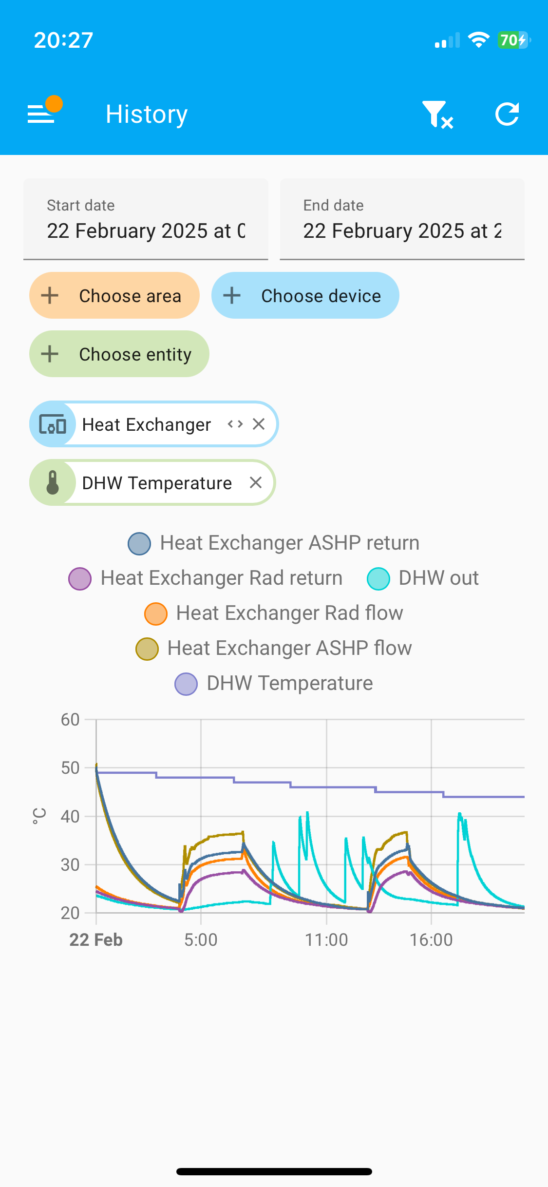
Today has been a warm. The photo shows the primary and secondary flow return temperatures. The dT is always about 4c. The 12kW Midea mostly runs at 50% capacity, but when the water is below target temperature it can get close to maximum output. DHW uses the full output. On a colder day it takes a while to reach target temperature. It can run 6-8 hours without pausing. Today we haven’t needed much heating.
As I said I would like to have the pump reversed temporarily to see what difference it makes. I think the dT might increase as well as the rad temperature (measured with a magnetic thermometer).
Phil
1 Like
Hi @Filipe,
Thanks for getting back to me with more info and please excuse me taking so long to acknowledge you - I’ve been struggling with the situation a bit, to be honest. Yes, we have the same installer.
Ours is a 10kW system and our house is smaller than yours but I’m sure with less good insulation. We “know” the heat pump by itself can’t heat the house when it’s properly cold and we kept the boiler as backup, mainly for power cuts (when I get a battery) but it has a separate thermostat so can swing into action when the heat pump isn’t capable of sustaining the room temperature.
Re the pump, would you mind telling me what model you used to have a what you have now? I was looking at whether I could replace with an even more powerful pump, but that might mean the pipe velocity gets too high and it gets too noisy - I think the main loop is only 22mm flexi so not easy to get a good massflow rate around the house.
Do you have isolation valves either side of the pump? Are there any non-return valves in your CH system? If no NRVs, and you have the isolation valves, perhaps you could turn off the heating, close those valves, undo the pump fittings, turn it over and refit it, then open the isolation valves again, and see how it performs then? I’m no heating system engineer though, so possible this is a bad idea.
Cheers ![]()
Initially a Milo Top-z was fitted then a Wilo Younis Pico. The former was very noisy. There is about 100W difference in the power consumption.
Our place had an EPC of C. I just let it run at 35c out and leave it to it. If it’s colder it runs longer and at 24/7 when freezing. We had all the rads replaced but the microbore copes as the distribution pipes seem to work. We have got used to slightly lower temperatures but the lounge is warm.
Phil
The Wilo Yonos Pico should display the power in watts, at least, and probably, in the latest model, the flowrate in m3/hr, this might be of some help to @madbilly.